A Steep Learning Curve
My wife has presented me with a sign that has just got JSN written on it. It is to remind me when I answer the phone to a ‘can you just do’ enquiry…… to Just Say No.
I try my best to live up to her expectations but sometimes something comes along that should really be a JSN job but which scratches an itch. You know what I mean. You think about it and you do all the right mental arithmetic in your head and the answer keeps coming back to the same – don’t even think about it. But the the other side of my brain is screaming at me … what a challenge, what a learning experience, what fun to have a go at it. Providing the asking party is aware of your thought process or lack of it and accepts that it might just go belly up and never come to fruition then why not ?
Back to the story – 10 days or so ago I had a call from David Pawley who is a turret clock expert extraordinaire to say someone he knew was after an escape wheel for a turret clock and was desperate. David passed on the details and a couple of days later the potential customer arrived on our driveway. After a suitably socially distant conversation and a rubber gloves inspection of the old damaged wheel …. I got sucked in and turned the JSN sign over to face the wall.
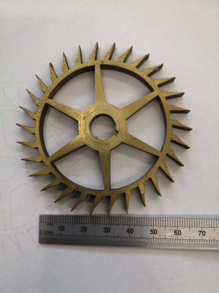
As you can see it is not an ordinary escape wheel and I had to delve into one of my favourite books ‘Wheel and Pinion Cutting in Horology’ by J Malcolm Wild FBHI in order to learn about Brocot Escape wheels. Malcolm is a great guy and his book should be on any clock experimenters bookcase.
The Brocot is no ordinary escape wheel. In fact it is a real challenge. Not a simple fly cutter job. Traditionally it would be cut in an indexing device such as a lathe with two different cutters, one for the curve and one for the notch. I didn’t have these so I thought I would probably upset the traditionalists and try to use CNC.
Read all about the adventure and see the result in this pdf download …….
Similar or related subjects : –
- Arduino Processor Reference Clock Accuracy
- 3D Printed Length Gauge for In Barrel Mainsprings
- The “Modern Clock” by Goodrich
- A Very Old Burgess Bandsaw
- Microset Timer interface using Fusion 360 3D model with Fusion Electrical
- Try again after update completes Fusion 360 Error Message
- Clock adjuster rod for measuring spring and fusee drive power
- Engineering Video Favourites Updated List
- Update notes on modifications to the Devon Sea Clock
- Burgess BK3 replacement lower blade guide