Probe and Toolsetter together on Tormach PCNC440

New Tool Setter Arrives

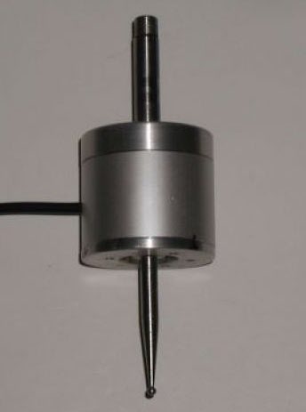
I recently bought a special offer price tool height setter from Banggood.   On arrival this seemed nicely made and robust and looked like a worthy addition to the armoury.   

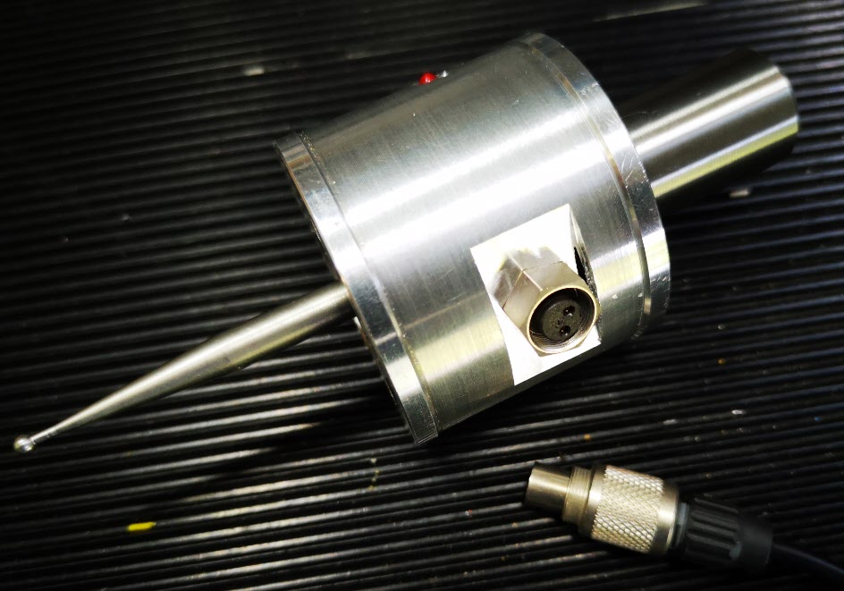
The Tormach PathPilot control software has facilities for tool height setting using such a probe.   I also have a Wildhorse Innovations probing tool for edge and centre setting.   Both these devices can be connected to the Tormach PCNC440 external input accessories connector which is  a 5 pin 180 degree DIN.

The input to the Tormach accessory socket is a 2 wire connection.   Sensing and operation of external tools like the probe and tool setter depends on the device having a normally closed connection that goes open circuit when activated (i.e. the probe tip moved or the tool setter pushed down).   The probes are in essence a single pole normally closed switch.

Frustration Sets In

After spending time having to keep swapping these two devices in and out of the accessory connector I figured there must be a better way.

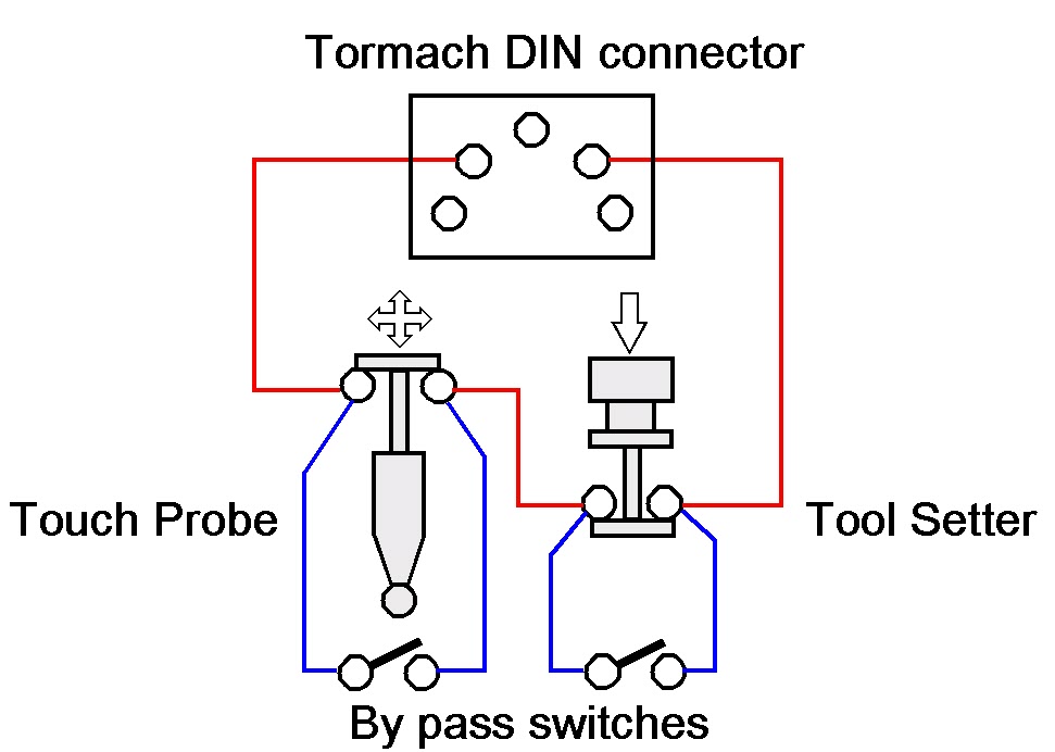
The Tormach does not care if you connect multiple probes at the same time provided they are all in series on an electrical loop to and from the two pins on the interface connector.   Any device when activated will break the loop and create an interrupt to the PathPilot software.   Because you will be in the area of PathPilot software that relates to the function you are measuring, the relevant probe will be the one you are intending to use.

The Solution

What was needed was a simple interface box that allowed the two probes to be connected in electrical series back to the two pins on the DIN connector.   I also wanted flexibility to be able to unplug either of the two probes and not affect the operation of the other.   This meant that on removal of either probe it would need an electrical short circuit across the pins of the connector from which the tool had been removed.

This could be done with a small by-pass switch, that is normally open circuit, connected across the connector.  You would manually close this switch if the probe is removed. 

This is fine so long as you remember to activate the switch when you remove the probe otherwise the sensing loop will see an open circuit and the software will get confused.

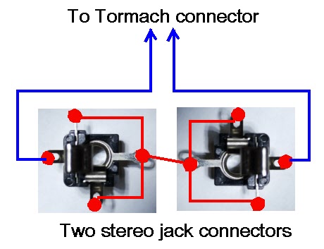
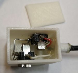
My solution was to use sockets for the connections that would automatically provide a short across their contacts when their mating plug is removed.   A good example is an audio style jack plug socket.   These come in various sizes (2.5mm, 3.5mm, 1/4″ etc).  Usually on these sockets the tip of the connector gets shorted to another contact when there is no mating plug in place.

I had some 3.5mm stereo jack plug and sockets to hand (either mono or stereo can be used as it is only a two wire connection) and these were simple to wire for this application.   

wiring two jack sockets for the probes on a tormach

I also ran a modified version of one of my standard 3D printed enclosures to mount them in and fitted a flying lead to a 5 pin DIN to plug into the Tormach interface.   A hot glued magnet onto the bottom of the enclosure allowed flexible mounting of the box somewhere on the Tormach body.  The only fiddly bit was replacing the existing connectors on the two probes with a 3.5mm jack plug.  (Don’t forget to the put the connector shell on the cable before you solder the wires in place ….. ).

finished dual probe input assembly

close up showing the wiring on the two jack sockets

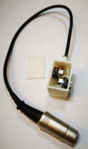
A neat solution and the problem solved.   Both devices plug into the box to perform their various probing functions into PathPilot.  Unplug one of the probes and its mating socket will automatically short out the probe connections when the plug is removed.  The remaining probe plugged into the other socket will continue to function.

Similar or related subjects : –

Tormach PCNC440 Fogbuster and Manual Oiler Service

Back from after a few weeks in France and back in the workshop.

Every now and then there is a project that is on the go and you can’t sit down and focus on it.  It is a sort of mechanical procrastination.   A reluctance to put the first pencil mark on the paper.   You then suddenly find all sorts of other things that you kid yourself are more important / higher priority and you get distracted.   You know that job will still be there but maybe tomorrow, not   today.   You suddenly develop a clear conscience about doing something else while you do some background thinking ….

This particular day started off by cleaning down the accumulated swarf (chips) in the 440 tray.  Really important job.  This led to a check behind the various 440 slideway bellows to see that all was well with the oiling mechanism on the slideways and the ballscrews.   X and Y were fine but Z was dry.  Not good news.   

The 440 is supplied with a manual oiler as standard.   This is a reservoir of oil and a pump/plunger which you pull out and release to initiate a slow pressure to the oil distribution pipes. 

Tormach manual oiler reservoir
View of the manual oiler mounted on the Tormach 440

 I checked the plunger and it didn’t feel like it was applying much pressure.   This is not the first time I have experienced this problem.   If I pumped a few times it felt better so something should have been happening at the oiling points on the Z.   I disconnected each of these where I could  and sure enough if I pumped hard enough some oil dribbled out but not with much pressure.   Something probably not right with the plunger ?

Squeezing round the back of the mill I removed the top of the reservoir (4 retaining screws), disconnected the oil pipe union and lifted the plunger clear.  The reservoir can be left in place sitting on the mounting bracket. 

There is a large end cap at the union end of the plunger cylinder which I removed and sure enough I could see a mangled O ring.   To get the plunger out you have to be a bit brutal.   You pull the T handle plunger back out of its housing against its spring using the handle as shown above and then grip the shaft with pliers so you can then twist the handle off.   What you don’t do then is suddenly release the pliers grip or the plunger will go into low Earth orbit under the pressure of its spring …

Having disassembled the plunger it was obvious that the O ring had failed quite badly.   Tormach support do not offer spares as the oiler is a third party item.  They do not know what size the O ring should be.   Checking in my box of miscellaneous O rings it looked like a 9mm ID, 3mm thickness part would do the trick.   Smearing the O ring with DC4 silicon grease allowed easy re-assembly into the piston bore and then back onto the 440.  I now had lots of pressure and oil was apparent trickling down the Z slideways and ball screws.  Job done.   No pumping needed, just one pull out of the piston handle was generating a slow release of oil to the key areas.

The job I should have been doing was still sat on the bench glaring at me but psychologically I was doing something more important.

Next problem was the Fogbuster air activation valve.  Under CNC control this reliably switched on but sometimes would not switch off when commanded to.  There are various forum discussions on this problem and many contributors just replace the solenoid valve with a different version.   Forum chat also recommended that electrical transient snubbers are fitted across various inductive loads in the Tormach control unit.   I had some of these in my stock box (Tormach offer a kit for this).   They are simply a series resistor and capacitor in an epoxy block.   They are fitted across any inductive device to suppress switching transients.   I dived into the control box and fitted one across the controller relay coil that switches the Fogbuster ON and OFF and another one across the outlet from the control box feeding the Fogbuster solenoid coil.   See picture below.

snubber inside tormach cabinet
Snubber across Fogbuster activation relay coil.  There is a second snubber fitted to the lower LHS contact which activates the air solenoid.   The other end of this snubber goes to the any ‘100’ connection which is mains neutral.

The problem seemed to be improved but still occasionally the solenoid did not switch OFF.

The Fogbuster solenoid has a clear housing over the activation coil connections and there is a LED inside this that comes on when the Fogbuster is switched on.   

Fogbuster activation solenoid
Fogbuster solenoid assembly showing the connection clear housing which plugs into the solenoid coil which in turn sits over the activating plunger assembly.  There is a screw in the LHS to release the electrical connection and the nut on the top releases the coil to reveal the plunger housing.

This connection housing plugs into the coil and the mechanics of the solenoid body and is released with a screw in the end.   Toggling the coolant ON and OFF via the PathPilot user interface I could see the LED responding correctly to the ON and OFF commands but occasionally the solenoid was not closing.   It was therefore not an electrical problem but mechanical.

On top of the solenoid housing is a single large nut which when released allows the solenoid coil to be lifted off.   This leaves two countersink screws which hold the mechanical plunger housing in place and if these are removed the plunger can be gently removed.   Inside the valve is very simple.   A central hole allows the air to pass through and when the solenoid is de-energised a spring forces the solenoid plunger to seal this hole.   I gave everything a thorough blast with compressed air and re-assembled it.   Care is needed re-assembling as there is a tiny O ring seal on the plunger cover.   The solenoid now responds correctly to the PathPilot commands.

Another tick.  Job done.  Warm glow.

That other job is still sat on the bench glaring at me ….

Similar or related subjects : –

Wildhorse Innovations Passive Probe

I bought one of the Wildhorse Innovations Passive Probes some time ago and it gets used occasionally (usually when I have dispatched another Haimer tip to happier hunting grounds).

wildhorse innovations passive probe
The Passive Probe as supplied by Wildhorse Innovations

The Wildhorse design is nice and simple and it can be bought with a ‘Tormach Option’ which is a cable with a ready fitted 5 pin DIN that is pre-wired to plug straight into the Tormach 440 accessories socket.   I have to say it did not talk to the Tormach PathPilot interface immediately.  I had to snipped the pull up resistor inside the unit to solve this.  When in use on the Tormach you have to designate the probe as Tool 99 in the tool table so as to be able to utilise the PathPilot probing routines (which are very good).

So where is all this going ?  Well it is a A to B to C progression …

I dusted the probe off to use the other day and as I had not used it for some time, I did a centring calibration of the probe ball point while mounted  in the Tormach spindle.   This is a real pain to do as the three centralising adjustment screws are on the bottom face of the body.  As a result you can’t see what you are doing and there is a danger of knocking your dial gauge in the process and having to start again.

This got me thinking about whether I could do this adjustment off line in the lathe.  This way the adjustment screws on the bottom face are readily accessible.   This seemed like a good idea except the umbilical cable is permanently wired into the unit so it needed to be protected from a disastrous wrap round the chuck.  Initially I wrapped the cable around the body of the probe and held it there with masking tape but it wasn’t ideal.

Watching the probe spin in the lathe chuck made me also realise that because I had mounted the probe in a Tormach TTS collet this was a waste of a collet. It might also be adding to eccentricity through using such a combination. So you see that one thing leads to another and to another.   A workshop wormhole.

A plan was made.  Fit a connector on the probe body to allow the cable to be disconnected and replace the existing mounting rod with a TTS equivalent.

Finding a suitable connector was a bit more tricky than expected in that there is not a lot of room inside the probe body and a connector that protruded too far would foul the spring loaded mechanics.   My search for a suitable connector combination Iead me to a 2 pin Binder rear mounted socket (Part Number 09 0074 00 02).  Being pedantic it should be a fixed plug as the connecting cable connector (Part Number 99-0071-100-02) would now have two exposed pins carrying a voltage.   The supplier only had the fixed socket version in stock so I conveniently looked the other way on that argument – the cable would rarely be unplugged so not likely to be a problem …

The circular body of the Wildhorse Probe is quite substantial.  When the connector arrived and I was ready to proceed, I took a picture of the existing wiring and then snipped the cable clear.  I enlarged the hole in the body wall to 9mm but then discovered that the mounting thread on the connector was not long enough protrude through the probe body wall far enough to pick up on the retaining nut.   To overcome this I milled a flat area on the shell outer surface.  The two connecting wires where then soldered in place on the fixed connector and then on the mating male connector on the free end of the cable.

wildhorse innovations passive probe internal view
Internal view of the probe after the Binder socket had been fitted

The next job was to make the new fixing rod.   I always try to have 19mm silver steel available in my stock box.  This matches the TTS collet outside diameter.  I decided I would make a new mounting rod with the silver steel and I would increase the threaded mounting hole on the probe top to M8 from the 1/4″ size as supplied .

wildhorse innovations probe top with new M8 mounting
Top cover of the probe inside view of the M8 inside the spring retaining counterbore

The larger diameter would provide a larger shoulder on the rod to tighten against the probe top. Using M8  would allow the stud mounting hole to still sit within the pocket that retains the pressure spring.   The rod was faced and turned to 8mm for 5mm or so and the M8 thread cut and undercut with a graver.   The other end of the rod was faced and then a 45 degree chamfer turned on it. The finished rod screwed nicely into the top plate and the body now seemed to run solidly square to the central axis.

Wildhorse innovations probe new mounting rod and body top cover
The new 19mm OD silver steel mounting rod and the outside surface of the top cover to which it is fitted.
Modified Wildhorse passive probe
Finished modified probe showing connectors fitted with the flat milled surface and the new mounting rod.

All operations were now complete and I mounted probe with its cable unplugged in the lather chuck with the new 19mm rod.  I mounted my dial gauge on the lathe bed and set about centralising the probe ball.  It was so much easier in the lathe with no cable to get in the way of things. Transferring the modified probe to the Tormach afterwards gave very similar centralising results.

Centralising the modified Wildhorse Innovations passive probe
Modified probe mounted in the lathe to allow easier access to the three centralising screws

So a typical workshop wormhole progression from job to job but as ever it was time well spent.

Similar or related subjects : –

PathPilot Upgrade to Version 2.x.x

I registered with Tormach for the free upgrade to the new release 2.x.x of PathPilot.  A memory stick arrived this morning with the new code.   It is fairly complex process but their documentation is quite easy to follow and understand.

All seems to have gone well with the upgrade except I can no longer see the shared drive for dropping files into nor can I get the Dropbox feature to load.  All of which suggests the network connection is not working but I not winning so far.  Gloom but not a disaster.  Fresh eyes another day.

Similar or related subjects : –

Verified by ExactMetrics