Gadget Builder Drill Point Inspector

A 3D Printed Version of John Moran’s Drill Point Inspector

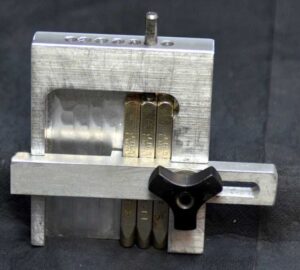
John Moran has an excellent website that details all manner of engineering projects. He is a keen advocate of four facet sharpening of drill bits and he details a Drill Point Inspector device for checking grinding results. I quite liked the concept and thought it would also be a useful asset for checking the condition of milling tools. The design uses a small inspection eyeglass magnifier lens that can be flipped from end view to side on view for tool tip inspection.

Those who know me through my blog will know that I am of a lazy disposition which tends to cause me to step back and look for an easy way to manufacture something. John’s design immediately suggested to me that a conversion to a 3D printed equivalent would be a practical solution. I also picked up on a comment that John made that you needed good light to be able to view the drill point clearly. As a result of this comment, the 3D design evolved with the addition of a simple LED illuminator. I also added a ‘right angle stop’ so that when hinged for side viewing, the lens was held more repeatably.

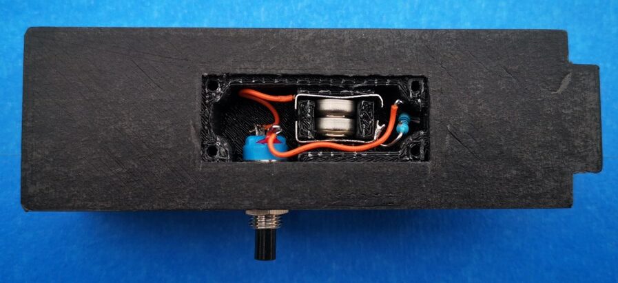
Because the inspector will only be used now and then, I opted for two small hearing aid batteries as the LED power supply together with a single resistor and switch. I printed two slots in the cavity for a pair of nickel silver battery contacts to sit in.

View into the battery and switch cavity. The battery contacts are bent pieces of nickel silver or tinplate

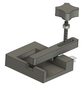
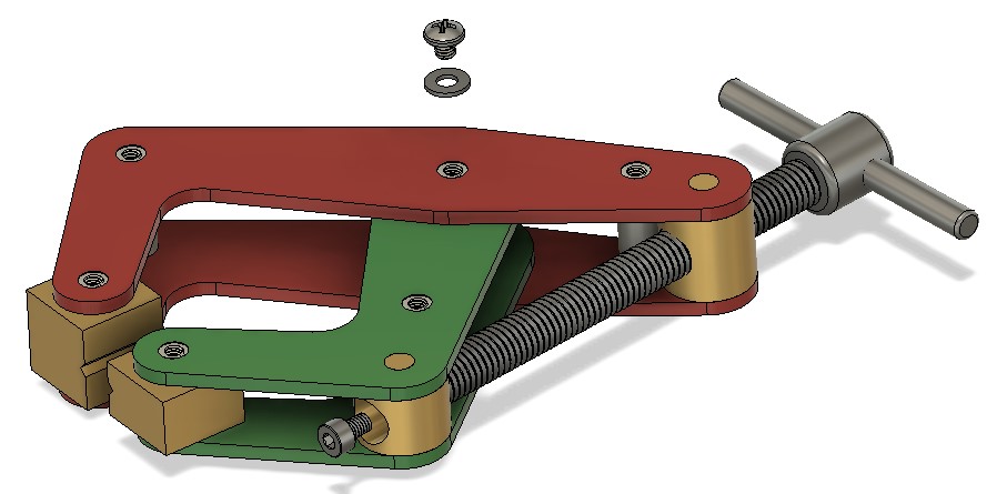
The design was modelled using Fusion 360. The two parts of the body were 3D printed. The Perspex viewing graticule was CNC milled to size and the reference comparison lines were also engraved on the CNC. The inspection lens is available from many sources on EBay (x30 21mm). The inspection screen mounting holes are 3D modelled. Here are a couple of shots of the finished model.

3D Model of John Moran's Drill Point Inspector showing the model flat for end viewing of the tool
Model hinged flat for end viewing of the tool (the LED is just visible)
3D Model of John Moran's Drill Point Inspector showing the model hinged at right angles for side viewing of the tool
Model hinged up for side viewing of the tool

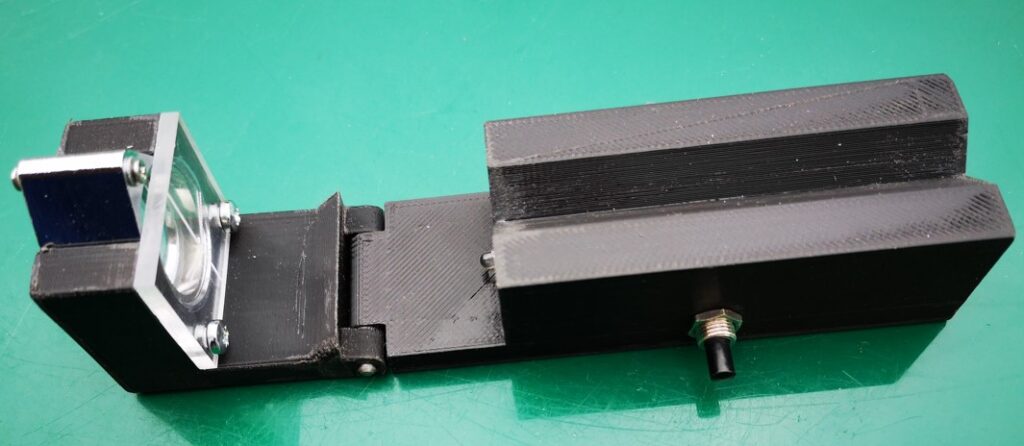
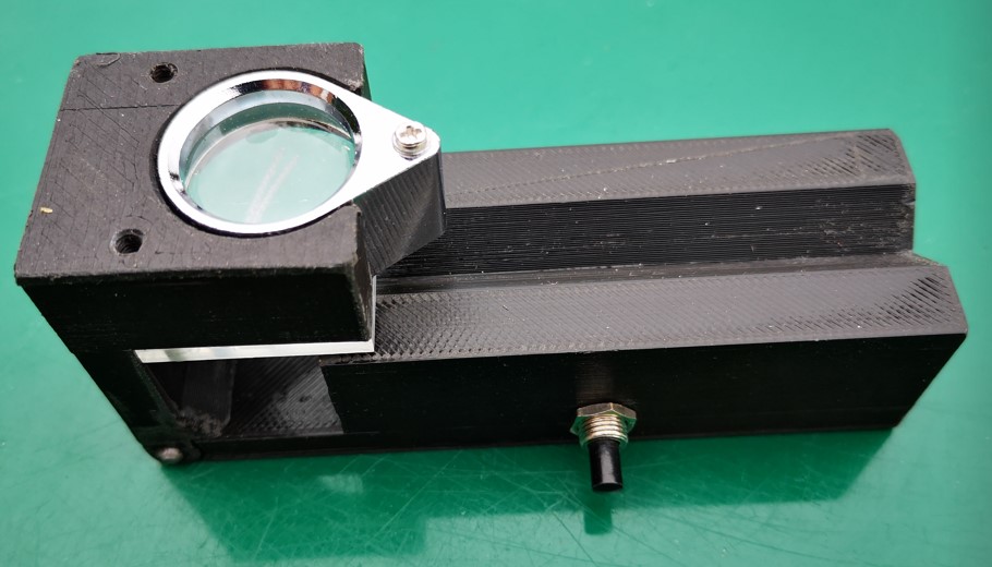
Note that the addition of the LED illuminator needs the modelling of a cavity on the bottom surface of the main body. When printing this part it will be necessary to have the printer provide support structures. I also printed a cover for the cavity but this could be an offcut from an old credit card or similar thin plastic sheet.

Once printed I found the parts needed slight ‘fettling’ to remove any surface striations on the V block section, in and around the hinge section and around the eyeglass mounting slot. That aside it printed fine and the parts went together easily. More to the point it works well and is a useful tool to have to hand.

The Fusion 360 file and STEP files for the main two model parts are available in the following ZIP file. If you need additional information please get in touch.

Links to similar or related post are listed below : –

Plastic heat sealer – a useful workshop asset

Clough42 has just posted making a protective cover for his plasma cutter control screen.   As ever with James it is engineering perfection with stitched corners.

My lazy way (as ever) is to make such items using polythene plastic sheeting and a heat sealer. 

This allows me to quickly make bespoke covers and pockets for all manner of applications.  Here are a few examples.

All my silver steel is stored in such pockets and has the size written on the sleeve using a Sharpie. 


The rear DRO scale on my VMB has an open ended pocket either side of the vice that acts as a concertina cover to keep cutting oil from affecting the scale reader.

So another useful tool to have available (without having to thread a needle).

Similar or related subjects : –

Deburring techniques in the home workshop

I don’t know about you but deburring a job after machining I find to be a real pain.  This is an important process not just for the look of the finished product but also to give personal protection from the resulting post machining sharp edges.

If it is a CNC job then a small deburring chamfer can be added to the CAM operations but that may not be always possible to easily implement.

A manual deburrer such as made by Noga is another option but on a large geometry job it is difficult to get a uniform profile to the edge chamfers when done with such a manual tool.   Inevitably you occasionally slip and scar the surface of the job and this really irritates.

Noga Deburring Set
Noga Deburring Set with internal and external cone tools

I do like the cone shaped tool for deburring holes. Incidentally Banggood offer blades and handles that are identical and interchangeable with the Noga range including a series of different sizes of the cone tools.  Here are a couple of links to get you in the right direction but there are numerous sources of similar products.

https://www.directnine.uk/products/sp1010-trouble-shooter-set-noga?gclid=CjwKCAjwq7aGBhADEiwA6uGZp8hHRPi6XvgIS6EHCAYGTcIHZUcLzjPcJ1UPpydpJ7Wg8D7EWQW5yBoCocoQAvD_BwE

Banggood DrillPro Equivalent Set

My most recent revelation was to get a deburring wheel.   I bought this from Zoro Tools.   It is a 6″ diameter wheel made by Bibielle.  There are quite a few other sources of this type of wheel. I made an arbor to mount the wheel into my drill press.  Deburring wheels are meant to be mounted on a horizontal grinding machine but bench space is tight in my workshop so it has to be a drill press mount as and when needed.  I have to say this is a joy to use and gives a quick clean finish to all cut edges.   The wheel also gets used for surface cleaning on dirty materials.   A useful addition to the workshop and one I wish I had discovered sooner.

Similar or related subjects : –

3D printed multiple punch holding tool using Fusion 360 Parameters

Using Fusion 360 Parameter Functions on this useful tool

I was pointed to this punch holder idea by a friend.  It was shown on HomeMadeTools.net and conceived by Andy Foale.   

Here is the link to the original post : –

https://www.homemadetools.net/forum/multiple-hand-stamp-helping-hand-65882

I thought it might be practical to make it as a 3D printed device and with a bit of guesswork came up with a first pass design in Fusion 360.   This was based on my set of punches which are 6.4mm square (1/4″) and 58mm long.   The design printed in PLA without any problems and the finished punch holder worked fine.  It uses one of my printed knobs as mentioned in another post.

3D printed punch holder per Andy Foales
Fusion 360 pictorial view of the finished punch holder

The success led to requests from others who liked the 3D print concept but had different size punches so needed the design tweaked to suit.

This looked like a good excuse to re-familiarise myself with Fusion 360s Parameter functions.   In short these allow you to program interrelated dimensions in a design through a series of basic algebraic functions.   The end result is a design that is fully flexible on the size of the punches to be used and the number of punches that might be judged needed as the maximum ‘word’ length.

The Fusion file is here in a ZIP file

punch holder v5

The Fusion file includes the holder, the clamping bar and the knob body.   You will need a short length of M6 threaded rod and a M6 nut to finish the knob.  The file is configured to 6mm punches, 63mm long but you can edit using Parameters function under Modify.  Clearly once you have the Fusion file you could run also run a CAM program and CNC cut the punch holder.

I am afraid this is a Fusion 360 file only.   If you aren’t a Fusion user (why not ??) and you want a STEP file creating to your punch sizes then email me and I can run it for you.

As stated in the original article, the kerning of the letters is defined by the punch cross section.

Similar or related subjects : –

Kant Clamp and Engineering Drawings in Fusion 360

Bondie Hacks is a YouTube site that I have on my YouTube listing and a recent video featured Quinn building a Kant clamp from a kit.   Needing some lockdown distraction I decided that I would attempt to build a clamp from scratch.   Searching on Google revealed a plethora of drawings and from these I distilled a plan of action.

I created a Fusion 360 assembly for my hybrid version. The clamp was made with 3mm steel side plates and the other fittings from various diameters of silver steel.   From the Fusion drawings I created two CAM programs to profile the side plates and the other fittings were all straightforward lathe work with the exception of the gripping blocks.  I made these in aluminium which I ran freehand on my manual mill.   If the clamp is to be used for welding then it is traditional to make the clamps and the screw from copper.

I opted to fasten the side plates with screws and washers but the pillars could have been peened in place.   This would have made replacement of the gripping jaws difficult however so screws seemed like a better option. 

The result turned out very well and I was pleased that I had made the effort.

Stylised Fusion 360 model of my Kant clamp

I have produced engineering drawings on Fusion previously but all were a bit ad hoc.   Fusion is capable of automating the process of creating drawings for each component but I had never got to grips with it.   Having created the clamp I decided it was a good excuse to dig deeper into the drawing process.

There are various YouTube videos on creating Fusion engineering drawings but the one that helped the most was by Bryce at Autodesk.   The key to the automation process is creating Templates.   This is really worth watching if you are debating moving up a level with the quality of your engineering drawings.

https://www.youtube.com/watch?v=Av7rFL-opVo&ab_channel=AutodeskFusion360

The video goes into detail on how to create a customised set of drawing sheet blanks with customised title blocks.   Having watched this a couple of times the mists began to clear. 

The result of my labours is the complete drawing set for my Kant clamp in the following pdf file.   Feel free to download and build your own.

Kant Clamp Structure Drawing v9

Similar or related subjects : –

Verified by ExactMetrics