I have been putting this off as I thought it would be hassle and in fact it was very simple.
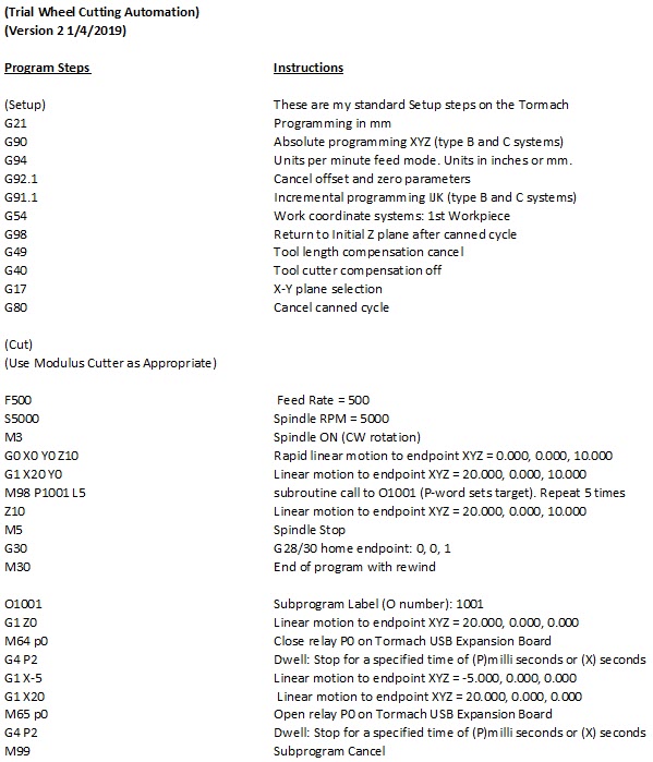
Here is the code which is the first time I have ever used a sub-routine.
The top section is my standard set up routine for the Tormach.
The middle section has some out of the way locations to try the idea so don’t get too fixated by these. The important bit is the M98 call for the sub routine, the sub routine name (1001) and the number of repeats (the L5 for five repeats).
The last section is the sub routine indicated by the O1001. The M64 command is specific to the Tormach USB Expansion board and it makes relay P0 in the box close its contact which in turn activates the Sherline CNC Rotary table to move one step. The cutter than moves across to cut the tooth and then returns whereupon the relay drops out (M65), waits and then closes once more to increment the table. Once five repeats have happened the M99 closes the sub routine and the program jumps back to the Z10 line in the middle section before stopping the spindle, homing and ending.
The joy of this method is that it is a simple edit of one line (the M98 instruction) to change the number of tooth cutting increments. I like it a lot.
Some fine tuning is still needed on the back and forth distances needed to clear the cutter through the wheel blank.
The normal test of the cut depth routine will still be needed before this could be run but once this is done it should be a sit and watch job. Hopefully.
I have yet to run a wheel in anger so I will let you know how it goes.
It has been a thoughtful morning on the Tormach wheel cutting setup.
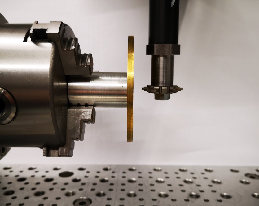
In order to cut clock wheels the first step is that I need to be able to set the cycloidal cutter centre line accurately on the centre line of the blank brass diameter. See the picture and description below.
Exaggerated mock up of the cutting setup showing a brass blank mounted on a super glue arbor and a cutter mounted in the Tormach Slitting Saw arbor. The centre line of the cycloidal cutter teeth sits on the centre line of the brass blank and cuts on the rear edge as seen above. After each cut the CNC rotary table increments the blank by one tooth ready for the next cut. (In practice the super glue arbor would need to be much larger in diameter in order to be more in keeping with the diameter of the brass blank and so ensure maximum support while the cutting was done).
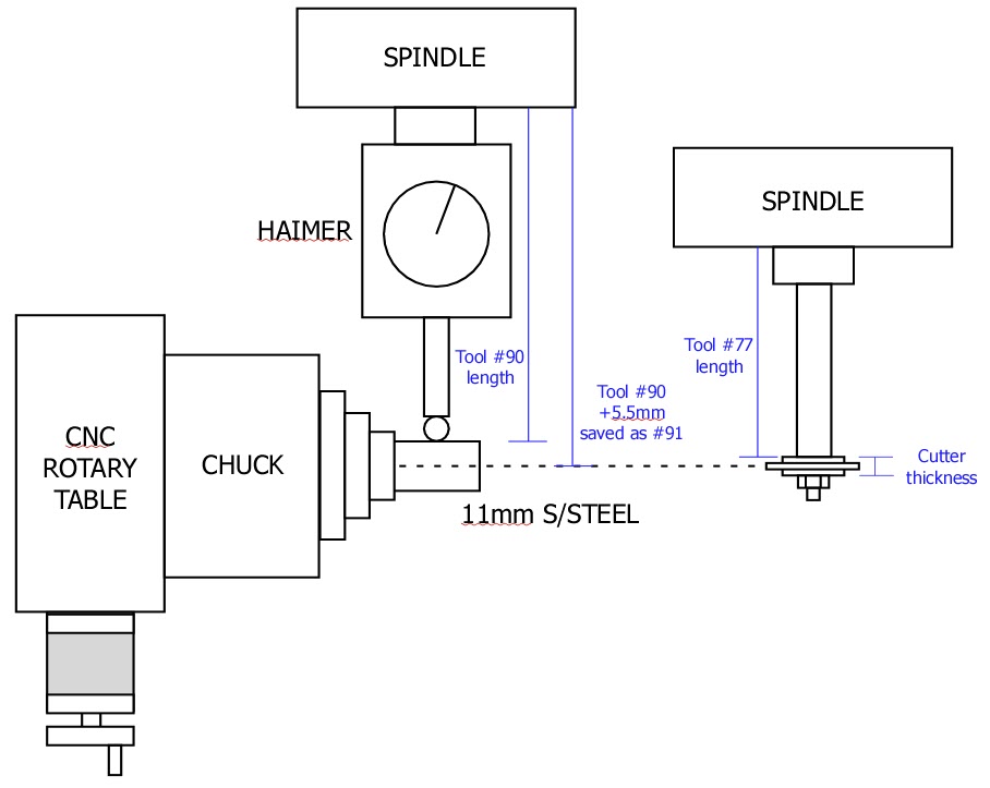
From previous posts you will know I have got the chuck securely and centrally mounted on the CNC rotary table and this assembly is in turn rigidly fixed on the tooling table. The position of the centre line of the chuck is now fixed relative to the tooling plate on the bed. The chuck and rotary table mounting bracket is sufficiently Woody over engineered to hopefully be repeatable. Likewise the distance from the spindle to the chuck can be repeatably zeroed using the Haimer and its associated tool table entry (#90).
Expanding this a little, if I put my favourite piece of 11mm diameter silver steel in the chuck and bring the Haimer down to contact it, rock the Haimer back and forth in Y to get the steel diameter peak, I can get a Z zero reading to the top of the steel. By creating a new entry in the Tormach tool table (#91) which is the Haimer length plus 5.5mm (the radius of the silver steel) I can use this virtual length stored as a new tool #91 to allow me to set the Haimer on the silver steel while actually giving me Z0 on the centre line of the chuck. So far so good.
As you might have read from an earlier post, the idea of using the Tormach Slitting Saw arbor to hold my cycloidal cutters would in theory create a repeatable tool length to the centre line of the cycloidal cutter teeth. Having this as a tool table set up in the Tormach would simplify setting the cutter centre to the centre line of the chuck and therefore the centre line of the wheel blank being cut. This is where the thinking drifted somewhat.
I created a new tool table entry (#77) that was the length of the saw arbor to the shoulder that the cycloidal cutter fastens against. I thought I could then follow the same routine as detailed above and add to this length the half thickness of the cutter and create a new tool table entry to match. This would once again create a length which would give the centre line of the cycloidal cutter.
That was fine until I measured my tray of cycloidal cutters to see what the thickness of the cutters were …… sadly consistent they are not. There seems to be no standard by manufacturer or diameter. I have cutters with thicknesses from 3mm through to 7mm. I could create a new tool table entry for each thickness but this is a recipe for a mistake when selecting the correct tool table entry for the cutter being used.
The simple solution I think is to use slitting saw arbor tool table length (#77) as the initial setting length to Z0 and then do a G0 Z-x.xx where x.xx is the half thickness of the cutter being used. Once Z has dropped to this reading the Z axis can be re-zeroed to run the wheel in question with the cutter in question now sitting on its centre line on the centre line of the chuck.
Simple diagram showing the concept of using the Tormach tool table facility to allow easy setting of the centre line of a wheel blank and cycloidal cutter centre lines
I hope that all makes sense …. I could of course just eyeball it and not try to be so fussy but when you have the tools to make things easier you might as well use them. I also need to look after my precious piece of 11mm diameter silver steel.
Another piece of the clock wheel cutting hardware completed.
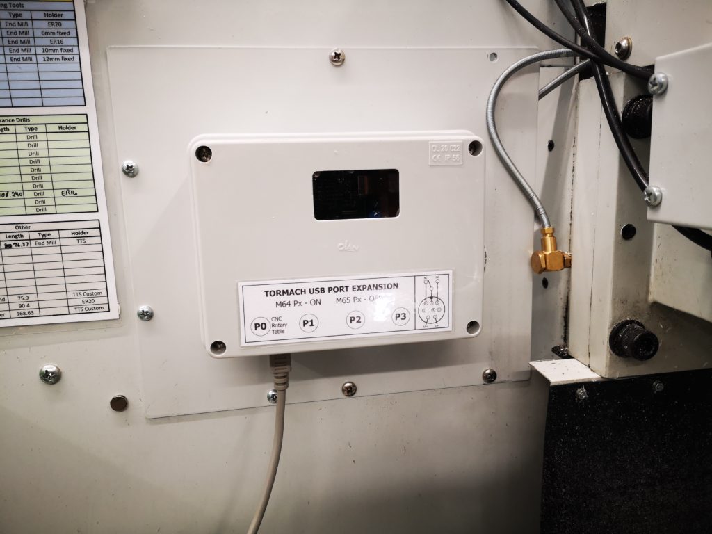
The Tormach USB expansion board is now boxed and the connectors wired to the board. I milled a viewing window in the box with a matching piece of perspex. This allows me to see the status LEDs on the pcb. Port #P0 is now dedicated to the Sherline CNC rotary table controller which requires a closure to increment the table stepper motor.
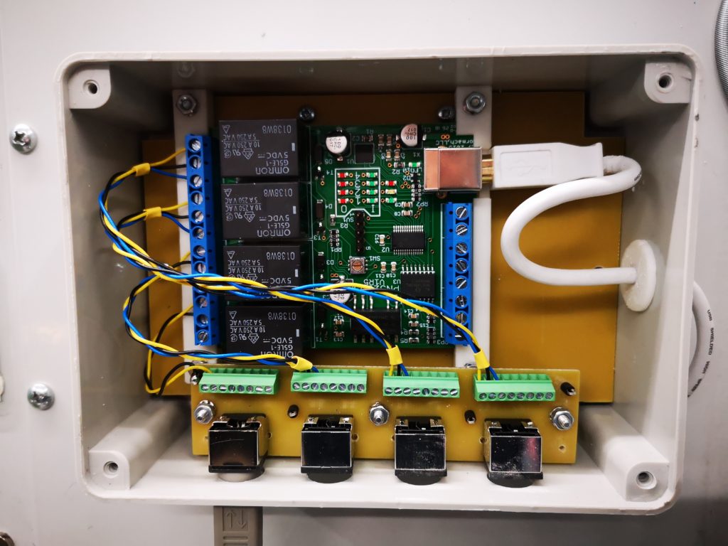
The connectors are all 8 pin MiniDIN which matches the interface on the rotary table.
Tormach USB Expansion card mounted in an IP55 enclosure and on the blanking panel where the ATC would normally be fitted.Internal view of the Tormach USB Expansion board mounted in its enclosure. It shows the MiniDIN connectors on the pcb milled using my vacuum table and also the lazy cable gland on the USB cable
I am slowly building up to being able to cut wheels on the Tormach PCNC440 with two possible methods.
The first is using Gearwheel Designer which is mentioned elsewhere on my blog.
The second route is more conventional using a PP Thornton or similar cycloidal tooth cutter and a dividing device on a rotary table. This later method is how wheels are traditionally cut in a lathe and there is a lot of information available on this.
In order to use the cycloidal cutters I need some form of arbor to mount the cutter in the Tormach spindle. I could simply turn a piece of steel bar to suit and mount this in a ER collet in the spindle. The downside of this simple approach is that every time the arbor was fitted into a collet the cutter would be at a different height from the table. I really wanted something a bit more repeatable as the centre line of the rotary table will always be the same so why not the cutter centering.
When I ordered the Tormach PCNC440 I also ordered the Tormach small rotary saw arbor (which to date I have never used). Pondering this last night I sketched up an adapter in Fusion 360 to allow an involute cutter to be fastened to the end of the saw arbor.
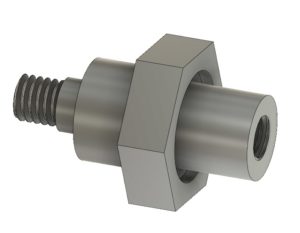
This is shown below. It is made from a piece of 19mm AF hexagonal steel bar with the hexagonal flats going to be used as a tightening it in place in the Tormach arbor. My Myford Super 7 when used with a 3 jaw self centering chuck is not bad on concentricity but for really accurate centering I swap the chuck for a collet face plate instead. This job was going to need both.
First operation was to turn the hex bar end that would screw into the arbor. This was done in the lathe chuck. It was a simple turn to a diameter and drill and tap the end with M6 to match the arbor mounting. The only pain was the arbor has a slightly protruding lip so I had to undercut the mounting face for this. Rather than trying to be clever I did it by hand using a graver.
While the hex stock was still in the lathe I roughly turned down the other end of the adapter to the primary diameter and slightly oversize for the cycloidal cutter bore diameter and then cut off the stock so far.
It would be important to get the cutter mounting running as square as possible so I swapped the lathe chuck for the collet plate and mounted the arbor end of the adapter in the collet. I carefully turned the shoulder for the cycloidal cutter diameter and then reduced the remaining length ready to cut a M6 thread.
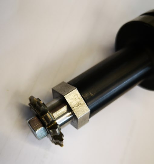
Here are a couple of images of the finished adapter.
Tormach TTS saw collet with my adapter and a typical clock wheel cutterAssembled cutter on Tormach TTS collet
I am pleased to say the idea went almost to plan and it runs very true in the Tormach spindle.
I was a bit over enthusiastic with the graver but this is of no consequence.
With hindsight the shank between the cutter and the hex section ought to be longer as this will restrict the diameter of the wheel that can be cut before the blank catches the hex section peaks.
One step closer to trying this method. The next experiment is to work on a sub routine in GCode to move the cutter back and forth while cutting and with the ability to easily program the number of cuts.
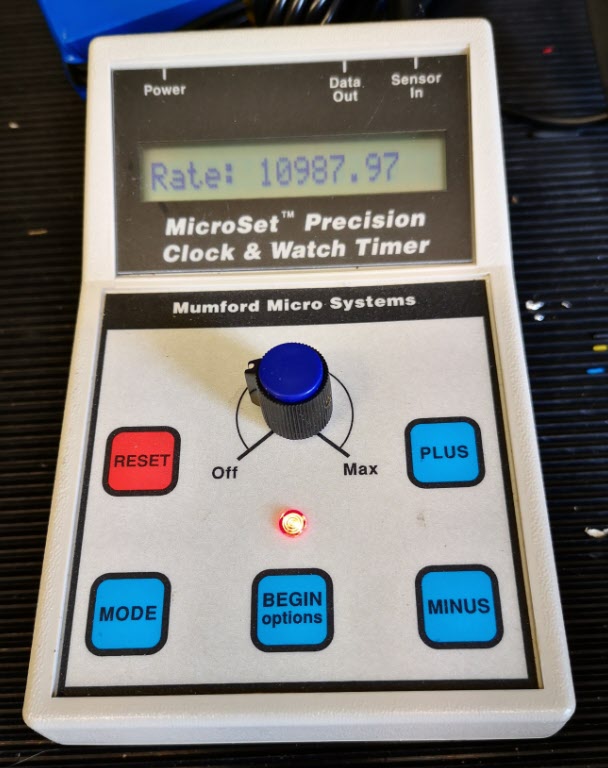
Some while ago I bought a Microset Timer from Bryan Mumford. This is a lovely device that allows you to monitor all manner of parameters on clocks and watches. It has an acoustic sensor to listen to the beat of the clock or watch and an optical sensor that creates and detects a beam of light that is chopped by the pendulum. From these simple accessories all manner of diagnostics can be done on the clock under inspection. If you want to know more I suggest you log into Bryan’s site. Bryan also has some videos which you can find on YouTube. You might also want to download and read a pdf collection of articles written by Chris McKay in the Horological Journal about using the Microset to fault find on Turret Clocks.
Microset Timer from Mumford Micro Systems
The Local Church Clock
If you are a regular reader of this blog you will know that I have got involved with the local church clock which is a Cooke of York movement. I have been working with a fellow engineer in the village to try to bring the clock to time and we are slowly getting there. Our last major breakthrough was finding the fly was lose on the gravity escapement arbor. Since tightening the fly the clock has been much more reliable.
There is a weight tray on the pendulum which has an assortment of coins in it where someone historically has been fine tuning the pendulum swing. Because the clock has been running fast by a few seconds per day we have been slowly removing the coins one by one to bring it closer to time. I think it is now at a point where we need to monitor it long term with the Microset.
Microset Upgrades
Bryan offers an upgrade to the Microset that allows a temperature sensor to be added to the recorded information. There will almost certainly be temperature changes in the clock tower so it seemed like a good idea to upgrade with the temperature option. This was ordered and duly arrived from Bryan and is now fitted. There is also an upgrade to allow the Microset to record data into internal storage in the Microset rather than depending on having a PC connected. I would be more comfortable leaving just the Microset in the church pendulum cupboard rather than my portable PC so I also ordered this upgrade.
It took me about an hour to do both upgrades on the Microset. The memory upgrade involves a chip change inside the device and the temperature monitor needs an additional 3.5mm jack socket fitting and wiring to accept the new temperature sensor. Neither is a difficult task but clearly need to be done carefully so as not to do any damage to the Microset. Bryan’s instructions are well written and illustrated.
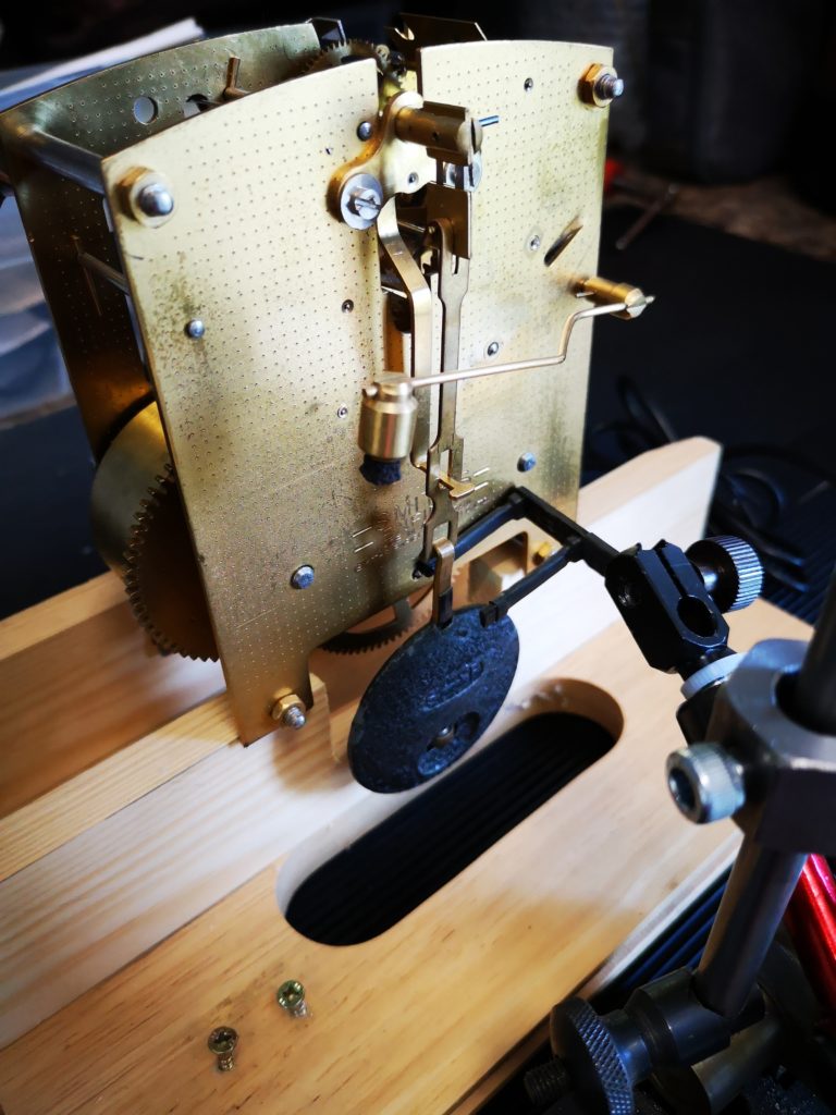
Since the upgrade I have been running the Microset on the bench with a Smith’s clock movement. (It is actually the one I stripped down, cleaned and rebuilt on my ‘Clocks 1’ course at the BHI). The new Microset facilities seem to work well and as expected.
Microset optical sensor monitoring a Smith’s clock mechanism
A New Sensor Needed – 1st Attempt
To implement measurements on the church clock the supplied optical sensor as shown in the picture above is not totally ideal. It has a very narrow gap between the transmit light source and the receiver detector diode which on a turret clock is not easy to use.
It is possible to get round this my fitting a cocktail stick or similar to the pendulum bob and using this to break the beam but it is a bit messy. I had picked up a bag of laser diodes and detectors at a local ‘ham’ radio junk sale and I decided these might form the basis of a new sensor which might be more useful to a large pendulum assembly. Bryan is a really helpful guy and although he does offer a larger laser sensor he was more than happy to help me with the required electronic interface to the Microset. The one proviso is that the amount of current drained from the Microset 5V power supply must be kept below 30mA.
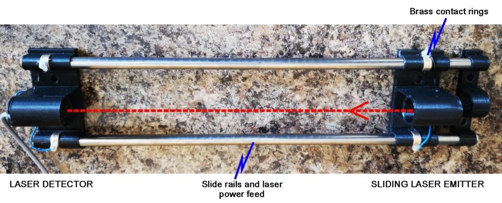
I set to and made the most elegant and over engineered solution for my laser sensor. This is shown below. The black mountings were designed in Fusion 360 and 3D printed on the Sindoh 3DWOX.
First ‘elegant’ laser detector for Microset timing instrument
The spacing between the emitter and detector is adjustable by sliding the transmitter along the steel rods. The power to the laser is also carried down the steel rods. A small DTC transistor provides the interface to the Microset and the 5V supply provided by the Microset is dropped via two diodes to power the laser. It works really well ….. but … when I went round to the church to install it I realised I should have checked one or two things first. The rating nut at the bottom end of the pendulum (used to make course adjustments to the pendulum length) was almost touching the floor of the pendulum cupboard. My wonderfully elegant laser detector would not fit under the pendulum to monitor the swing. A serious re-think was needed. The gap was so narrow that at best I will only be able to get a piece of 16 SWG aluminium sheet or PCB underneath the rating nut.
A New Sensor Needed – 2nd Attempt
I did say I had a bag of laser diodes and detectors so a new version would be possible and I could then save the posh one for more public facing activity.
As mentioned above I decided to use PCB as the base board. This is shown below.
Mk11 Laser Detector Specific to local church clock with little clearance from rating nut to floor
This has the advantage that I can use the copper surface to mill tracking into it to aid the wiring. The downside is that it is quite flexible and therefore possibly not stable enough to keep the laser aligned with the detector diode. To resolve this I soldered strips of nickel silver (could have been more PCB) either side of the centre line as shown but leaving a gap for the pendulum swing.
I designed a common holder for the laser and detector diode in Fusion 360 and 3D printed two of these on the Sindoh 3DWOX.
The finished detector assembly still had a tendency to flex so I stuck some old pieces of credit card on the lower surface, one at each end before the mount and a large piece in the middle. This seemed to cure the problem without adding significantly to the base thickness.
Microset Display
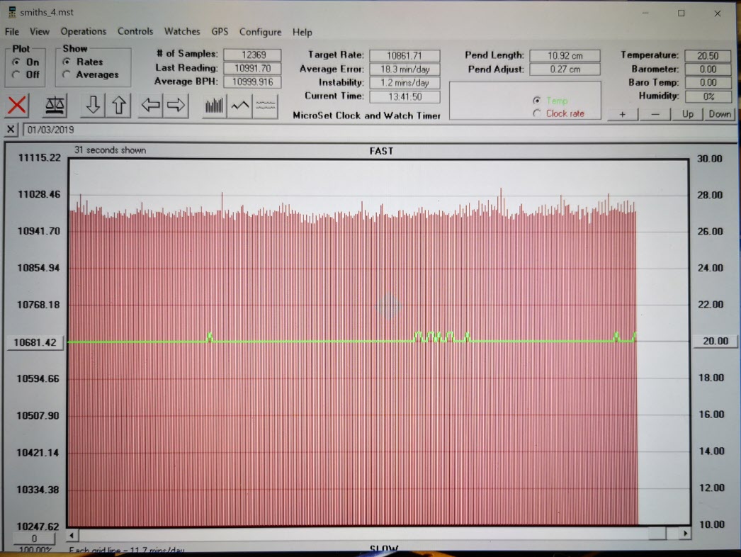
When plugged into the Microset all seemed to work well. Here is a typical PC display of the Microset data.
Microset Data Display showing the data from a Smiths clock mechanism and also the green line showing the temperature
I now need to get it installed in the church tower.


 It is made from a piece of 19mm AF hexagonal steel bar with the hexagonal flats going to be used as a tightening it in place in the Tormach arbor. My Myford Super 7 when used with a 3 jaw self centering chuck is not bad on concentricity but for really accurate centering I swap the chuck for a collet face plate instead. This job was going to need both.