OK so this is nothing radical but worth adding to the armoury.
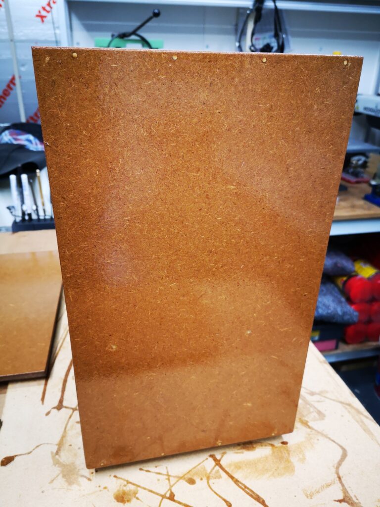
I am in the process of making a protective box for my clock bushing tool and the various accessories that are used with it. I had some 9mm MDF board in stock that looked a potential candidate for this. The only problem with a 9mm board thickness is that this didn’t leave much margin for error using standard 6mm dowels and I did not want to use screws or nails to hold my box together.
The solution I came up with was to use 3mm bamboo barbeque sticks as dowel substitutes. These are incredibly strong in sub 25mm lengths.
I did cheat however and did not try fit them in blind holes but instead drilled the mounting holes through to the outside surface. It still looks OK and has resulted in a very strong structure.
Image of the side panel of my home made clock bushing tool protective box. This shows the bamboo barbeque stick dowels bonding into the edge of the 9mm MDF components (the ‘dowels’ can be seen as white dots along the top and bottom edge). The MDF is finished with Yachting Varnish. You can see what a messy painter I am ….
I have had a few requests for a compendium of all my spreadsheets created over the months and years. This will be a work in progress as new sheets are created and then added. Here are the current contents.
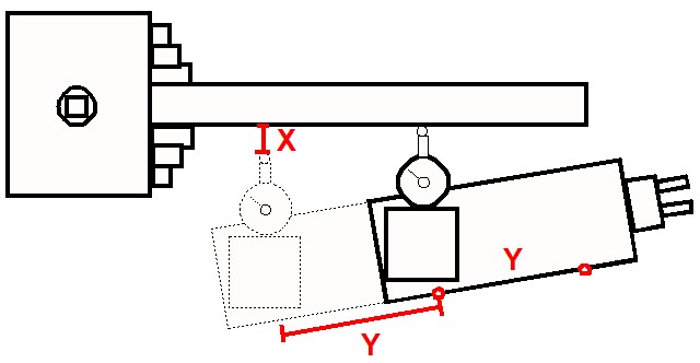
In the course of making miniature taper reamers to bore injector cones I initially struggled to set the compound slide angle sufficiently accurately. DAG Brown’s book details using geometry to set the angle and once I grasped this concept things improved. This is shown below and uses the Sine Rule.
The application method involves using a dial gauge set to zero when touched off on the workpiece. The cross slide readout is also zeroed at this position (this can be on a DRO if fitted or the Vernier scale). The compound is then moved a known distance along the workpiece before measuring the displacement needed on the cross slide to bring the dial gauge back to zero. Here is a picture. This is not rocket science and has been detailed on many other sources.
Graphical view of the setting technique.
By making the Y distance as large as possible, the resolution of the angular setting will be improved. The distance for Y is best chosen to sit symmetrically either side of the ‘closed’ position of the compound. By standardising on a fixed Y distance the process can be made more repeatable for day to day use. Angles can be committed to a lookup table and hence my idea to create a spreadsheet as detailed below.
On my Myford Super 7 I decided that a distance of 50mm for Y gave me a reasonable travel distance (+/- 25mm on the closed position). This could be accurately measured using the compound Vernier scale dial (my Myford is a metric version).
To speed up the measurement process I scribed a 50mm spaced start and finish mark together with a datum mark on the side of the compound. The datum mark is on the protractor ring. These ‘scratchings’ are shown below. (The extra cap head screw and pin are the Geo Thomas ‘Red Book’ compound lock mods).
These markings remove the need to tediously count revolutions of the Vernier scale when making an angular measurement. I simply set the Vernier ring to zero at one mark and then keep winding the compound until the second mark is reached. I then check once again on the Vernier ring scale. The movement distance is then finely adjusted to zero by referencing to the Vernier ring scale zero. If you have a DRO on the compound this process becomes more flexible.
With all the setup tasks decided, the spreadsheet was created. I chose to have 0.5 degree steps through to 69.5 degrees (it could be extended beyond this). I also added two standalone look up calculations. One to allow a single angle to be spontaneously calculated and one to back check a measured X distance to find its associated resulting angle. The latter would allow set up errors to be quantified to allow a knowledgeable ‘tap’ of the compound in the right direction.
The spreadsheet can use any units for Y as the table will automatically reflect this change. Here is a screenshot of the table based on my chosen value for Y of 50mm.
The spreadsheet .XLSX file can be downloaded from this link.
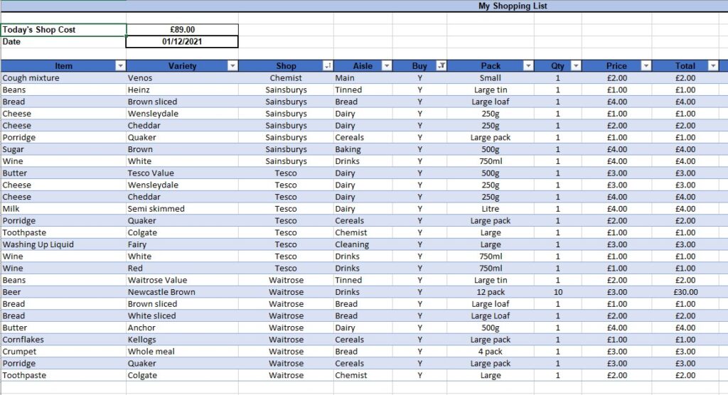
This one is way off beam …. an enquiry for help appeared on the Model Engineering Workshop forum for a simple shopping list when buying groceries etc.
Excel has a facility to create a special version of a spreadsheet called a pivot table. In short this is a table that contains columns and lines but each column has a header that is automated to allow sorting of the table by that particular column. Not only does the column sort the full table but you can refine the data to just show and sort lines of interest. It is easy to use, no macro skills needed just click and sort. I love pivot tables …. well lets be honest I love Excel. So many possible uses for lines and columns.
The table allows you to have multiple entries for the same produce from different stores and for each store there is a location in the store and a price for the item in that store. So you can have different sorts of bread from different stores and all at different prices. To go shopping you put a ‘Y’ in the Buy column. Here is a screenshot (with random pricing I entered to try it out).
Once you have the ‘Y’ on the items of interest you get a price for the total shop. You can then click on the Buy column header down arrow and a dialogue box comes up that asks how you want to sort. By selecting just the Y entries you get a unique list for today’s shop. Once you have the Ys only, you can then sub sort by store and by aisle or location in the store. Once you have something that suits your expedition, print the active area by highlighting and using Print Selection and off you go with a prompt of what you should be looking for as you walk round each store.
There are no macros, no complex formula and anyone can use it.
OK it is a bit over the top for shopping but as the years pass we tend to forget what we went to the shops for in the first place. We also tend not to see the price creep from week to week. Maybe it will help someone ?
More importantly the pivot table could be modified to become a workshop asset register. Change the headings to Item, Manufacturer, Source, Location, Price Paid (the price you paid or the price you told your wife you paid ?) etc and you begin to look organised. The grim reaper arrives and your family now have a listing of what you had hidden away, where precisely and at what value. They are now a step ahead and they are less likely to get ripped off by the workshop clearance bandits. Think about it, it could be time well spent.
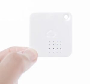
I have installed a network of low cost wireless sensor tags to monitor our homes here in the UK and also in France. These are really useful little devices that measure temperature, humidity and motion such as a door opening.
They store their readings and can be interrogated via the Internet to see a profile history. They also have limit alarm trip options that push messages to email to let you know if anything untoward is happening. The product website is here.
Image of a tag device
As examples of their use, here in the UK we have one fitted inside our freezer to check that the temperature is within limits. Should the freezer fail or the door be left slightly ajar we get a message.
In France we have one installed inside the spa pump cabinet to check the temperature over winter to check that the pipework does not see freezing temperatures. This works in conjunction with a greenhouse tubular heater that is also in the spa cabinet wired to a frost stat set to 5C degrees. If the temperature drops the pipes are protected by the heater coming on. If the AC mains fail the heater will not come on and the sensor tag warns us to ask the neighbours to visit and check the electric distribution panel as we do experience frequent power outages.
Under normal circumstances the tag internal CR2032 battery will give a reasonable battery life approaching 12 months. These are not normal circumstances however and due to COVID we have been unable to visit for over 12 months. As a result all the tags at our house in France have dead batteries. Their use inside freezers and outside in the cold degrades the battery life achieved. This got me thinking about fitting a larger battery pack to the tags in France to help longer battery life monitoring while we are absent.
My solution is not elegant but functional. I have wired an external battery pack containing two AA batteries to the tags. The battery box is a commercial item and is available in packs of five on EBay. They come fitted with an ON/OFF switch and more than enough cable to connect to the battery contacts inside the tag.
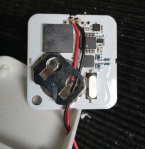
The tag case can be sprung open with a fine screwdriver or wood chisel and the PCB removed. The dead battery can be slid out of the PCB battery holder. There are a string of five module probing lands at the foot of the PCB and after some checking I discovered that two of these are connected to the battery holder contacts. The external battery pack wires can be fed into the case via a 3mm hole in the top edge. The wires then pass through the old battery holder down to the bottom of the board and are soldered in place. The tag is re-assembled, batteries fitted and switched on. The tag will bleep if all is well.
Internal view of the tag and how to wire the external battery connections
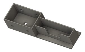
This electrical modification works but it is physically a bit gangly and scruffy. A few minutes on Fusion 360 produced a simple 3D printed holder to contain the battery pack and the tag. This has a slot so the temperature sensor is not obscured and a sprinkling of holes to allow physical mounting as appropriate.
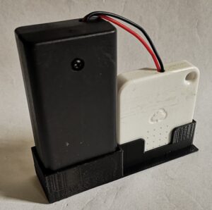
Fusion 360 pictorial view of the tag and battery holderFinal assembly of the battery pack and the tag. The dot on the battery pack is a retaining screw.
In theory this modification should dramatically improve the operational life of the tags between battery changes but time will tell whether it is borne out in practice.