Lots of activity to be documented and posted but let’s start off with a short note. Not earth shattering but might help someone somewhere.
I had the bright idea of using Micro USBs as a connecting medium on a couple of projects. This was driven by the need for a 5 wire connection. The design was finished and I dug out the Micro USB to Micro USB cable that had been bought in for the project and connected things together. All the LEDs went out on my project circuit board. Gloom.
After buzzing the cable through I found that on a standard Micro USB cable the Sense pin is linked to the Ground pin. There are not 5 independent and isolated cores as you would expect. Just four. What to do ?
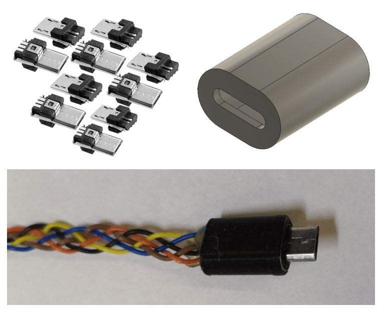
By chance I had some Micro USB connector ends with solder tabs but no shells. I did not have any flexible small diameter cable with 5 cores. After some discussions with my other half she offered to plait 5 independent cables together for me as a cable form. These were soldered to the Micro USB ends. Two small end caps were quickly designed in Fusion 360 and took 10 minutes to print on the 3D printer. Job complete and project back up and running.
Custom Micro USB 5 core cable components showing solder terminal end connectors, 3D printed shell and plaited 5 core cable courtesy of my wife.
I have had two IT related issues of late. Both involve devices on the house networks that have ‘locked up’ and needed a hard bounce – a complete mains power down, wait and switch on again. One of these was in our house in France and one at home.
The one in France was a lock up of the broadband router. Clearly once this is down all comms stop and we do have various monitoring systems in place that are important. Searching online came up with a GSM based mains switched outlet. This simply plugs into the a wall socket and the device to be controlled plugs into it. You need to fit a PAYG SIM into the device and then you talk to it with your standard mobile using SMS messages from anywhere there is a mobile phone signal. As the SMS usage will be very low, a GBP10 SIM will last for ages but it is important to remember that if a PAYG SIM is not used for 3 months it automatically gets cancelled. Fortunately the device does acknowledge back via SMS each command received so it is possible to maintain SIM activity remotely. The device has a number of facilities such as temperature measurement and activity scheduling. This has now sorted the French Connection and I can bounce the router anytime it misbehaves. Here is the Amazon reference.
The home issue was on a device on the home wired network which was important to keep running. Very occasionally and usually at an inconvenient moment it would lock up and the only way to reset it was a hard bounce. The device is a pain to get at to do this and if we were away from the house even more so. Fortunately the WiFi router at home is reliable so all I needed was a WiFi equivalent of the GSM device mentioned above to give the offending device a controlled hard bounce. Amazon offer one such device which was easy to set up and works a treat. For those interested it accepts speech commands via Alexa etc
Some while ago I happened upon wireless tag net which market a range of simple to use wireless tags for temperature, humidity, movement etc. These devices use short range wireless comms to a wireless node connected to the house broadband router. Once activated the tags can be monitored and controlled via the web. There are a number of extensions to this using other technology devices which all in all make them rather attractive and useful.
I decided our house in France would benefit from the use of these devices and this would allow us to monitor the house from the UK. I bought a package of 5 temperature/humidity/movement tags and a single moisture tag for the garden.
These are really easy to set up and add to your web portal. Results are graphed for you to see trends etc. Really nice simple and useful product.
I could put lots of pictures up but the best thing is to follow the link as above and read all about it. Deliver to the UK was quick but got hit for import duty and VAT.
As part of my purchase package of the Tormach PCNC440 I ordered their granite block and height caliper. This meant I could measure and set tool heights directly into the tool table on PathPilot via the caliper USB connection. See the image below which shows the granite block, caliper and the associated dongle box.
This concept works really well and saves manual entry typo errors when measuring tool lengths. I have found one problem however and that is the caliper eats batteries at an alarming rate. These are CR2032 button cells which are not dramatically expensive, but the cost does start to add up. There is the added frustration of the caliper potentially not functioning at a critical moment when a new tool needs to be measured.
It struck me as strange that a device talking via USB should be dependent on a battery when 5V is available from the USB interface. The fact that this did not happen suggested to me that the connection from the interface box to the caliper did not have through continuity of the 5V supply. This wasn’t surprising given that the caliper runs from a 3V cell.
Investigation
I connected the caliper via a standard USB cable directly to a variable power supply connected onto the 5V power pin on the USB cable. Varying the power supply from 0V to 5V showed that the caliper would work quite reliably over a range of 3V to 3.8V but above this the display would blank or just show 8888 at high intensity so masking the actual reading.
I found a couple of 1N4148 signal diodes in my component stock and put them in series with the 5V feed from the power supply to act as a series voltage drop. This brought the working voltage delivered to the caliper back into the 3V to 3.8V range where it functioned without any problems.
Implementation
So the question was now as to how to implement this modification elegantly ? ….
Be warned that the modification to be described involves a change to the USB dongle box supplied with the caliper and as such will invalidate any warranty. Mimic what I did at your own risk.
The dongle box has four screws on the bottom cover and removing these reveals the controller pcb. Take care not to loose the three blue switch activator rods in the process. On inspection of the pcb, the USB cable entering the box has all four standard USB connections but the cable exiting to the caliper has the 5V lead (red) disconnected.
I found a pin quite close by to the output lead that was marked 5V. This was a possible feed for my two diodes. On measuring this I found it was at a lower voltage than expected suggesting that there was perhaps some circuitry between this point and the incoming 5V. I therefore chose to ignore this and looked instead to the input connection cable. I found the +5V connection (red) as it connected to the pcb. I connected the two diodes in series to this cable termination and then ran a connecting wire (orange below)across the board to the 5V output (red) cable which was previously not connected.
These modifications are shown below albeit with hot glue over the diodes and connections.
Modification to Tormach digital caliper dongle box
This completed the modification. I checked out all the voltages while the pcb was still outside the box and also checked the caliper was still working. I replaced the pcb back into the box and screwed the lid in place.
One final thing I did which is not necessarily essential but felt like a good thing to do, was to put a tantalum capacitor across the former battery contacts in the caliper battery compartment. This would act as decoupling should there be any ripple on the new supply to the caliper. See the image below. Note that the tantalum capacitor is polarised and its + lead goes to the former + battery contact (on the right as shown below).
While this is a potentially useful thing to do, it has the disadvantage that you cannot put a battery in the caliper if you want to use it ‘off line’ when not connected to a USB port. You could however plug it into USB charger via the dongle lead.
The other minor thing I did was to fit a small cable tie to retain the caliper connector in place as I found it easily become disconnected.
On putting the setup all back together, the caliper was working well with a nice contrast to the LCD display. Tool table updates work just as they did before so no issues there.
If you do this modification you might want to experiment with different diodes or the number of diodes needed to the drop the voltage from 5V to within the caliper normal voltage range. Note that you need to use small signal silicon diodes which will have around a 0.6V voltage drop per diode. Don’t use Schottky diodes as these generally have around 0.2V and so you would need at least 3 times as many to achieve the same overall voltage drop. You could try LEDs as they all seem to have different voltage drops but they tend to need a high drive current which if this is the case, makes them unsuitable for this application.
You could of course go really elegant and build a small integrated power supply chip into the dongle box such as the AMS1117. These are available in various fixed output voltages including a 3.3V version (which is popular for Arduino projects and available from Amazon). You can also buy a ready made 5V to 3V module based on the AMS1117 from Amazon. I like the AMS1117 and used the 1.5V version in my power supply modification to the Shumatech DRO systems.
Here is a printer friendly (and slightly updated) version of this article : –
Working on small items requires me to use optical magnifiers such as the Rolson one with swap out lens. These inevitably pick up scratches and other marks.
I recently bought some Polywatch polish from my clock parts supplier to polish a plastic clock dome which was looking pretty rough. Polywatch transformed it to the point of where it looked almost new.