Adding a LAN connection and other small modifications
From the title you will have guessed that I could not resist the temptation to buy an X Smart 3 while they were on special offer at GBP299.
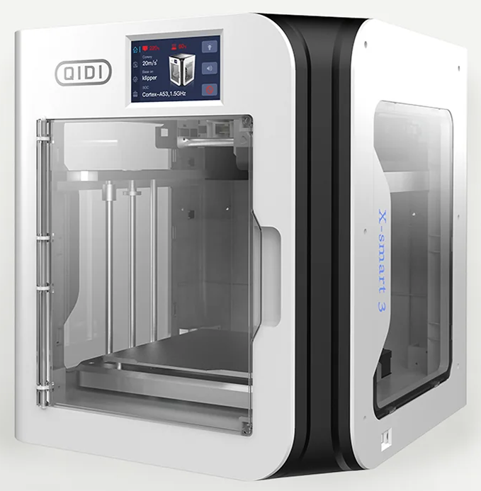
The X Smart 3 is a lovely little machine. It prints excellent high quality models at a very fast speed. My testing suggests around a third of the time as on my Qidi ifast but of course it has nothing like the same chamber build volume.
I have had some issues with the X Smart 3, some of which were finger trouble on my part and some that needed recourse to Qidi’s excellent support team.
Attached to the link below is a ZIP file that has the full write up detailing my modifications to the X Smart 3 to add a LAN socket, modify the processor fan operation and to add extension feet to raise the body of the printer to allow more air flow. The ZIP file contains the PDF document and two STL files, one for the extension feet and one for a printed template to aid positioning the hole for the LAN socket.
Note that the LAN connection will not appear on the printer control panel but is visible by the Qidi Slicer application. The IP address allocated will be automatically defined and you will need an application like Fing to discover what this is. The control board will be discovered as a Raspberry board.
Since the above write up I have progress on a HEPA filter housing for the X Smart 3 rear fan. Below is a write up on this and some changes I also made to my i-fast. Note that since posting this write up I moved the rear fan filter housing inside the chamber so that the fan is pulling air through the filter rather than trying to push it through. This worked out nicely with the rectangular shaped filter housing.

I have also made a replacement top cover with a large HEPA so air can get in and out of the chamber to mitigate having to leave the lid off.

Update – Fan Noise
The only remaining frustration with the printer is the power supply fan noise. This is present all the time the printer is running whether under full print load or just on standby. Unlike the ifast the X Smart 3 only has one power supply. It is therefore impossible to get the power supply to switch off when it needs to be on to run things. Contrast the ifast where it goes completely quiet. There are suggestions that there maybe better substitute power supplies that have proportional speed fan control driven by the supply current demand. I debated this but decided there would still be noise even when backed off.
My solution is a bit steam age. I bought in an Alexa compatible AC switch. I now tell Alexa to turn the printer on and off. Much easier than trying to get round the back of the printer to the power switch.
On the subject of Alexa devices, I also bought in a Google/Alexa air quality monitor so I can check the VOC level around the printer. This seems to be quite sensitive and suggests the HEPA filter modifications are working.
Links to similar or related post are listed below : –
- Hybrid 3D brass threaded insert tool
- Tap shank adapter for 4mm AF hex drivers
- Qidi Slicer auto support error on my part
- Qidi X Smart 3 MCU comms failure
- Superb Qidi Technical Support
- Qidi X Smart 3 revised fan installation
- Qidi X Smart 3 tweaks
- Qidi X Smart 3 special weekend pricing
- Stop losing Qidi ifast 3D prints down the chamber front gap
- Fitting a Bento air filter to a Qidi ifast 3D printer