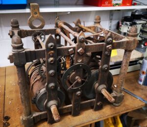
I have mentioned my activity on the Thwaites clock in a couple of blog posts and I can now confirm the work is complete.
The Thwaites clock as received before work commenced
This has been an interesting challenge and I am pleased with how it has worked out. Once again I am impressed by the way that modern techniques and technology can all play their part in achieving a result that once upon a time would have been impossible using traditional circumscribed knowledge.
Of late there has been a long thread running about Fogbuster use on the MEW forum. This set me thinking. The forum debate centred on whether mist lubricant or flood coolant was more or less healthy. For hobbyists the consensus seemed to favour the mist coolant. This was with the proviso that the jet and coolant mix is carefully balanced. An interesting point was made about ensuring the air stream was pointing away from the operator to avoid blowback. If all is good you should not be able to smell the lubricant. (N.B. I use QualiChem Xtreme Cut 250C at around 8% dilution).
The installation on my Tormach PCNC440 is fine with respect to blowback at the operator. Both nozzles are on flexible mountings and can be easily directed towards the back of the mill. (See prior post).
My installation just completed on my Myford Super 7 is not quite so perfect. I was using a T slot at the back of the saddle as the nozzle mounting. This meant the nozzle was playing on the back of the workpiece and towards the operator. Perhaps with hindsight not the most healthy option. OK so I don’t use lubricant on the lathe that much as most of my work is brass and aluminium so maybe less of a critical issue. Because of the infrequent use I wanted the Fogbuster to be quickly demountable until the next steel job comes along, hence the T slot idea.
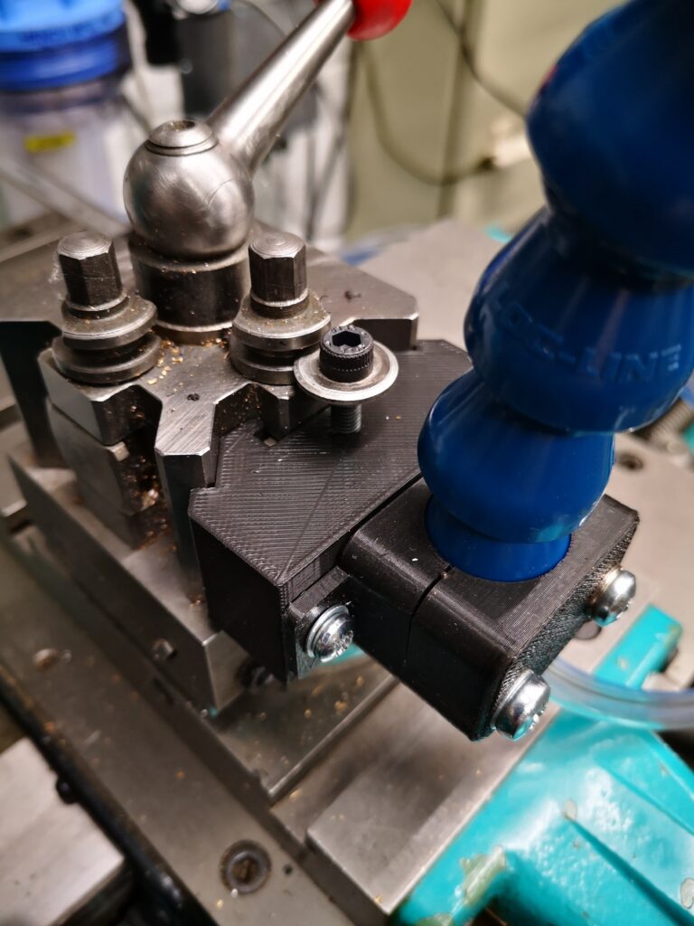
I have a Myford Quick Change Toolpost fitted on the Super 7 which has two tool holder positions at right angles to each other. It struck me that the Fogbuster could be mounted in the QCTP unused slot. This would allow the air jet and lubricant to point forwards towards the workpiece. Normally I would have the empty slot on the far side face so a boring bar can be dropped into place. By rotating the QCTP through 180 degrees the spare slot would sit nearest the operator and be ideal for the Fogbuster.
I didn’t really want to dedicate a steel tool holder to the Fogbuster so I created a 3D printed version. This picked up on the prior mounting holes I had modelled in the flexible clamp.
I needed to make sure my 3D printed profile was a good fit in the QCTP so after fully modelling it I moved the time line in Fusion back to the profile extrude and reduced this from 26mm to 5mm and ran a test print on just a 5mm depth version. This allowed a quick print to be done which gave me feedback to do some minor edits. The timeline then was dragged fully forward and a full size print run. Try doing that as easily and quickly in steel ?
The pseudo toolholder 3D print ran in around 90 minutes and looked and fitted well. To finish off, I turned up a small clamping button to match the normal clamping and height adjustment screw on the QCTP.
Hey presto a new Fogbuster forward facing mounting ready to go.
Fogbuster mounting using the Myford QCTPOverview of Fogbuster mounting on a Myford QCTP
One of the posters that Jimmy Diresta sells says “I’d rather have it and not need it than need it and not have it”. The saying is apt and often strikes home. This is not just in terms of larger workshop assets but also in the small scheme of things like workshop tooling. You know the time you spent making a jig for a job and thought ‘all that extra time and effort to just make that and what do I do with the tooling now ?’
I think it is a saying that is close to the heart of many hobbyist no matter what the medium you are working in. It does explain why our workshops are full of ‘stuff’ that we accumulate on the ‘just in case’ basis. How many screwdrivers do we really need ? The answer of course is ‘one more’.
I believe there should be a sub clause to Jimmy’s poster – “Needing it and Having it yet not being able to Use It”.
I have a Cowells ME90 mini lathe which is a beautiful piece of engineering and I seem to remember it was my first real mechanical engineering purchase. For 364 days of the year it sits looking forlorn at the back of the bench asking to be valued, loved and used. When it is called into use it is indispensable. Usually. On a recent once in a blue moon 365th day when it and only it could perform a task for me I found the drive belt to the headstock had perished. You could almost see the grin on the ME90s face. Gottcha mate, serves you right for not looking after me.
Thankfully the drive belts are standard sewing machine belts (#MB410) and are readily available both direct from Cowells or numerous sources on the Internet including Amazon. A replacement was ordered and it arrived quite quickly.
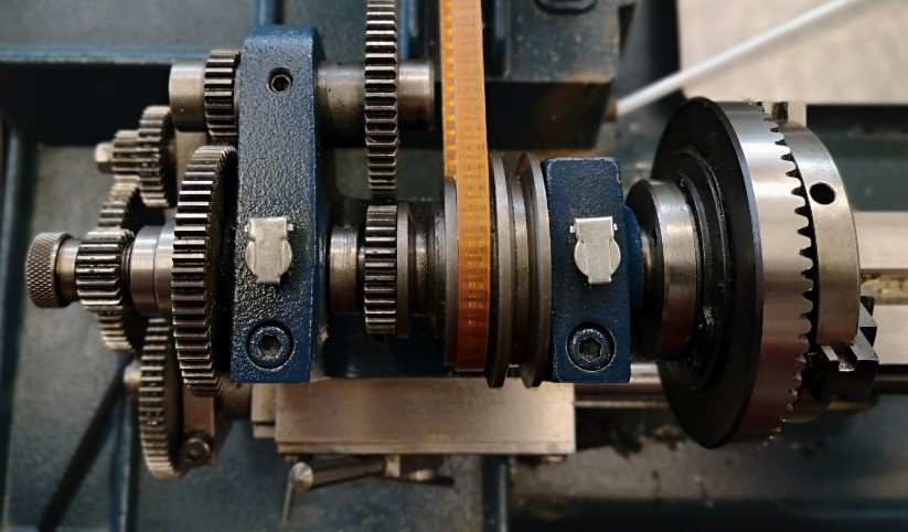
Now to the nub of the problem – how to fit the belt ? Looking at the headstock it suggested that maybe the whole assembly had to be lifted off and split but the cap head screws for this which went down into the baseplate did not want to budge. I looked at the spindle and it seemed to have differing diameters that at first glance would not allow it to be removed out of the bearing mounts.
Cowells ME90 headstock assembly for reference while following the belt replacement instructions working left to right
Rather than risk a regretful step I emailed Cowells and very quickly got a support reply from Colin. For all future intrepid belt changers here are his instructions : –
The only way to fit the belt between the 3 step pulleys is to dismantle the headstock assembly.

Its quite simple really:-

Start at the left hand side of the headstock.

1, Unscrew the knurled gear retaining nut.

2, Pull off the 20 tooth gear ( be careful not to lose the tiny Woodruffe key beneath it).

3, Unscrew the round adjuster nut that butts against the large (64t) gear. -You can use a pair of pliers/grips if you put some emery cloth in their jaws.

4, Slacken the M5 grub screw ( or take it out) in the 64t gear.

5, Pull this gear off. (If it is reluctant to budge then, its probably due to a burr underneath- see below for advice).

6, Slacken the M4 grub screw( or remove) in the little collar that abuts the headstock pulley inside the headstock channel.

7, Slacken (or remove) the grub screw in the central vee of the headstock pulley.

8, Slacken the tension on the two bearing adjuster journals- these are the large cap head screws you see on the top face of the headstock body.

9, It should now be possible for the headstock spindle to eject toward the tailstock.

Clean all parts thoroughly and re-assemble in reverse.


If you have trouble removing the 64t gear then, make sure all grub screws are removed as above. Screw back on the knurled gear retaining nut and with a hide mallet, gently tap the headstock spindle toward the tailstock.
As I said in my thank you reply to Colin, I felt like a hybrid version of ‘stupid boy Pike’ and ‘Rodney you plonker’. (UK sitcom specific joke).
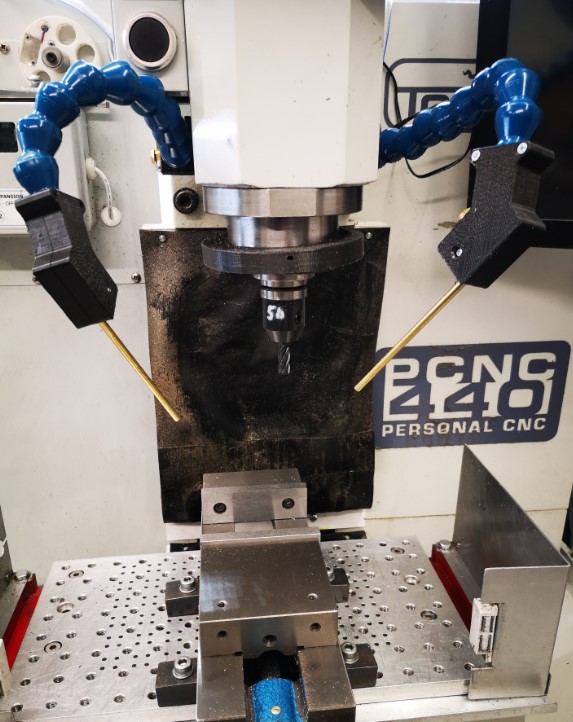
Apart from working on the Thwaites clock parts, I have also done an upgrade to the mounting of my Fogbuster coolant nozzle installation on my Tormach 440. This was triggered after viewing and being impressed by Clough42’s idea. The Fogbuster is a great way to clear swarf and apply coolant. The Fogbuster is normally supplied with a magnetic mounting arm but James’ modification uses LocLine gooseneck components to provide a much more flexible ‘aiming’ capability.
Something to be aware of – James recommends a download from GrabCAD for the 3D files of the two halves of the nozzle holder. These had been uploaded by contributor Br BRB. These were apparently publicly available via GrabCAD. James slightly modified these and was offering them as a free download from his Thingiverse folder. He has since had to remove them for download due to commercial issues. BrBRB has also removed the original files from GrabCAD and is seeking to sell these as finished items. I was lucky to have downloaded the files before the politics cropped up. I still have the downloads.
James also advocates fitting a second identical nozzle to the Fogbuster to avoid coolant and air shadowing. I contacted Fogbuster in California and a very helpful lady called Rachel organised an upgrade kit to provide a second feed from my existing coolant reservoir.
Dual Fogbuster coolant nozzles on Tormach PCNC440 using Clough 42 flexible nozzle idea
It turned out Rachel was from Bristol UK so it is a small world and we had a good chat. I have fitted both nozzles to the Tormach. With a pressure of around 10 to 15 psi, the reservoir feeds both nozzles very well and is a huge improvement in use.
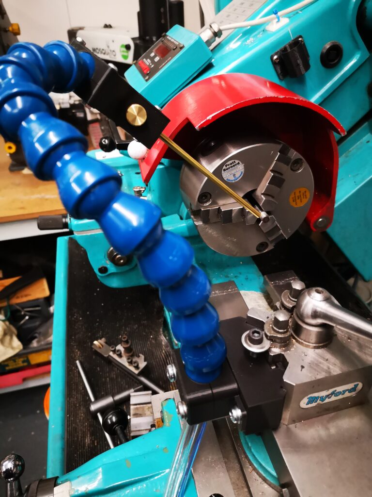
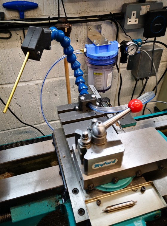
As I was facing a shipping charge from the US I figured I might as well top up the package so I have also splashed out on a baby version of the Fogbuster to fit to my Myford lathe. This uses the same idea but with slightly different mounting that fits into the T Slot on the Myford saddle. I already had the 3D model of the T Slot strip from the ‘bits tray’ installation.
Baby Fogbuster mounted on my Myford Super 7 saddle based on the Clough 42 flexi nozzle idea
Another pair of incremental asset improvements successfully installed. I suppose I had better get on and make something now.
Back to ‘the clock’ …
UPDATE 2 : – The 3D printed ball joint kept working lose on both the milling machine fogbuster mouunts. The more I tightened the screws to grip it tighter, the more the 3D components began to crack and give way. The solution was to fit brass inserts into the 3D prints. Problem solved. Incidentally there is a good review of such inserts on CNC Kitchen.
A few posts ago I talked about using 3D printed soft jaws for work holding in CNC operations. This method does not replace conventional aluminium soft jaws where high accuracy machining operations are to take place. Instead it is intended to allow second side ‘decking’ of what would have been excess stock on the material blank that had been used for work holding.
I am currently creating missing components for a Thwaites turret clock. I had finished the pallets and I now moved onto the new escape wheel. The design was created in Fusion 360 and integrated the pallets and the escape wheel together so the critical geometry was compatible.
The brass blank for the escape wheel was a 1/4″ brass block which I managed to hold tightly in the machine vice with a 1mm thickness of gripping stock. (I don’t have Tallon grips or similar so I have to be generous). I machined the wheel and was left with this 1mm to skim off the reverse side of the wheel.
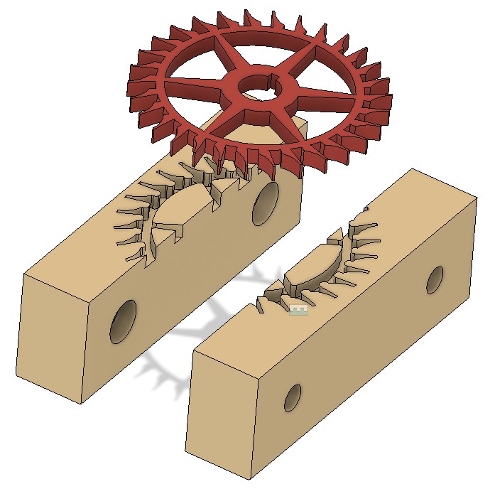
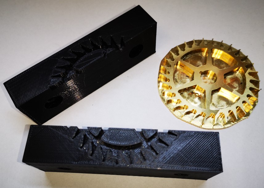
I did not want the teeth on the new wheel to get damaged when gripped in the vice so the 3D printed soft jaw concept appealed. The PLA would provide grip. The teeth on the wheel could bite into the PLA without suffering any damage.
I had already created a single blank soft jaw In Fusion 360 for the previous pallet holding job. This like it would be fine to accommodate the wheel dimensions. I simply had to import two of these into the new soft jaw design (not forgetting to ‘Break the Link’ so the jaw models could be edited). I projected the wheel onto the soft jaw’s face and added a 0.2mm positive offset border. I almost made the mistake of forgetting to invert the wheel as the soft jaw image must be a mirror of the Fusion top side view of the design to be gripped.
Fusion 360 view of the Thwaites wheel projected onto the PLA 3D printed soft jaws.
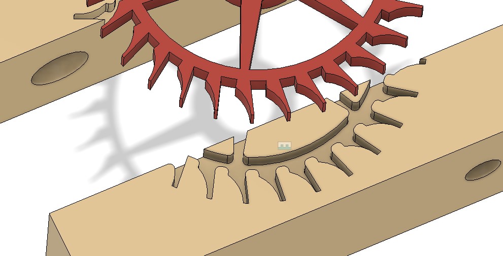
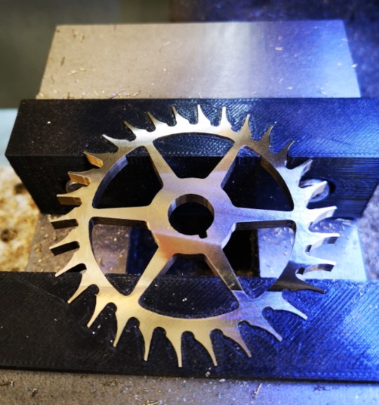
The finished brass wheel did not accurately reflect the geometry of the Fusion design. This is because the resolution of the tight corner CNC operations were limited to tool sizes. I added fillets to all the ‘sharp’ edges in the soft jaw image to accommodate this. I also had to do some tweaking of the inter jaw spacing 3D joint to reflect the wheel diameter and the amount of grip I judged might be needed.
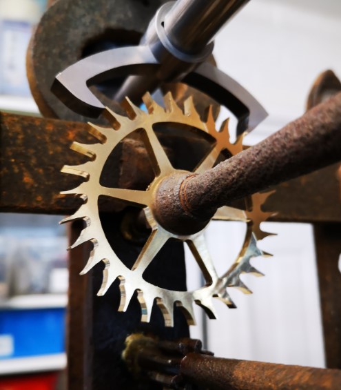
Close up view of the fillet modifications to the projected sharp corners of the wheel outline into the soft jaws.Soft jaws and the brass wheel ready to be skimmed. The residual original square stock has been roughly trimmed around the wheel circumference.The jaws were printed and I have to say were somewhat cosy tight around the wheel geometry. When the jaws were mounted in the machine vice, the wheel was not going anywhere and the excess backing brass was skimmed off quickly and easily with no apparent movement of the wheel in the jaws.Finished wheel mounted in the jaws after the excess work holding stock had been skimmed off.The finished escape wheel and pallets mounted in the Thwaites clock
I am really warming to this technique. It is quick and easy to implement and any mistakes can be quickly rectified with a new 3D print without having to remake aluminium versions. I like it and recommend it.