I have mentioned my activity on the Thwaites clock in a couple of blog posts and I can now confirm the work is complete.
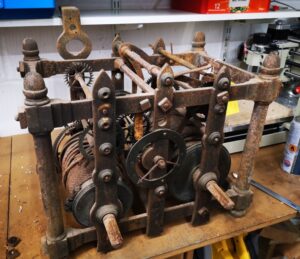
The Thwaites clock as received before work commenced
This has been an interesting challenge and I am pleased with how it has worked out. Once again I am impressed by the way that modern techniques and technology can all play their part in achieving a result that once upon a time would have been impossible using traditional circumscribed knowledge.
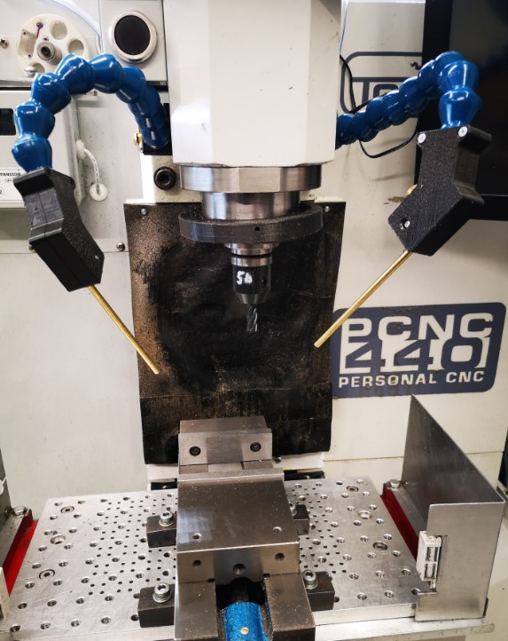
Apart from working on the Thwaites clock parts, I have also done an upgrade to the mounting of my Fogbuster coolant nozzle installation on my Tormach 440. This was triggered after viewing and being impressed by Clough42’s idea. The Fogbuster is a great way to clear swarf and apply coolant. The Fogbuster is normally supplied with a magnetic mounting arm but James’ modification uses LocLine gooseneck components to provide a much more flexible ‘aiming’ capability.
Something to be aware of – James recommends a download from GrabCAD for the 3D files of the two halves of the nozzle holder. These had been uploaded by contributor Br BRB. These were apparently publicly available via GrabCAD. James slightly modified these and was offering them as a free download from his Thingiverse folder. He has since had to remove them for download due to commercial issues. BrBRB has also removed the original files from GrabCAD and is seeking to sell these as finished items. I was lucky to have downloaded the files before the politics cropped up. I still have the downloads.
James also advocates fitting a second identical nozzle to the Fogbuster to avoid coolant and air shadowing. I contacted Fogbuster in California and a very helpful lady called Rachel organised an upgrade kit to provide a second feed from my existing coolant reservoir.
Dual Fogbuster coolant nozzles on Tormach PCNC440 using Clough 42 flexible nozzle idea
It turned out Rachel was from Bristol UK so it is a small world and we had a good chat. I have fitted both nozzles to the Tormach. With a pressure of around 10 to 15 psi, the reservoir feeds both nozzles very well and is a huge improvement in use.
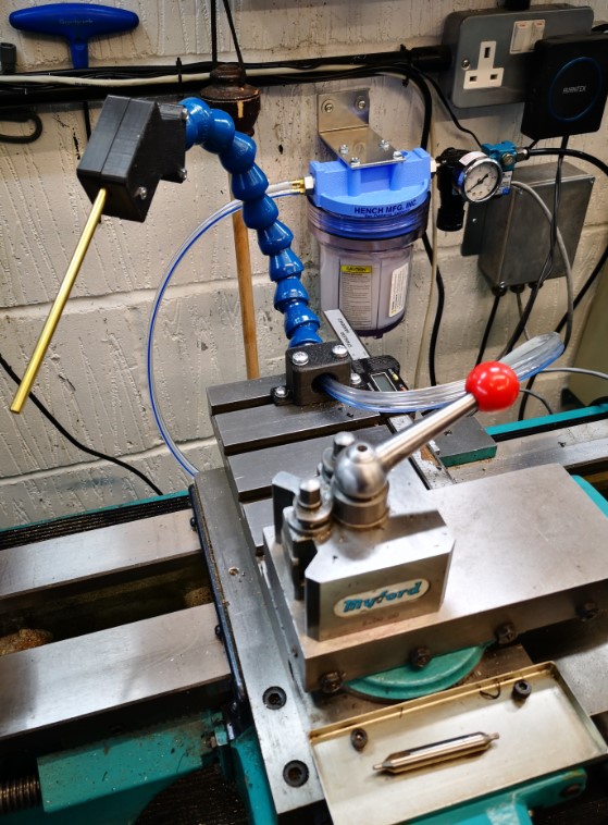
As I was facing a shipping charge from the US I figured I might as well top up the package so I have also splashed out on a baby version of the Fogbuster to fit to my Myford lathe. This uses the same idea but with slightly different mounting that fits into the T Slot on the Myford saddle. I already had the 3D model of the T Slot strip from the ‘bits tray’ installation.
Baby Fogbuster mounted on my Myford Super 7 saddle based on the Clough 42 flexi nozzle idea
Another pair of incremental asset improvements successfully installed. I suppose I had better get on and make something now.
Back to ‘the clock’ …
UPDATE 2 : – The 3D printed ball joint kept working lose on both the milling machine fogbuster mouunts. The more I tightened the screws to grip it tighter, the more the 3D components began to crack and give way. The solution was to fit brass inserts into the 3D prints. Problem solved. Incidentally there is a good review of such inserts on CNC Kitchen.
A few posts ago I talked about using 3D printed soft jaws for work holding in CNC operations. This method does not replace conventional aluminium soft jaws where high accuracy machining operations are to take place. Instead it is intended to allow second side ‘decking’ of what would have been excess stock on the material blank that had been used for work holding.
I am currently creating missing components for a Thwaites turret clock. I had finished the pallets and I now moved onto the new escape wheel. The design was created in Fusion 360 and integrated the pallets and the escape wheel together so the critical geometry was compatible.
The brass blank for the escape wheel was a 1/4″ brass block which I managed to hold tightly in the machine vice with a 1mm thickness of gripping stock. (I don’t have Tallon grips or similar so I have to be generous). I machined the wheel and was left with this 1mm to skim off the reverse side of the wheel.
I did not want the teeth on the new wheel to get damaged when gripped in the vice so the 3D printed soft jaw concept appealed. The PLA would provide grip. The teeth on the wheel could bite into the PLA without suffering any damage.
I had already created a single blank soft jaw In Fusion 360 for the previous pallet holding job. This like it would be fine to accommodate the wheel dimensions. I simply had to import two of these into the new soft jaw design (not forgetting to ‘Break the Link’ so the jaw models could be edited). I projected the wheel onto the soft jaw’s face and added a 0.2mm positive offset border. I almost made the mistake of forgetting to invert the wheel as the soft jaw image must be a mirror of the Fusion top side view of the design to be gripped.
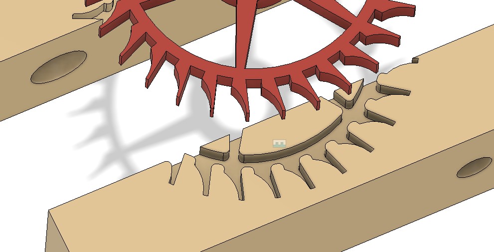
Fusion 360 view of the Thwaites wheel projected onto the PLA 3D printed soft jaws.
The finished brass wheel did not accurately reflect the geometry of the Fusion design. This is because the resolution of the tight corner CNC operations were limited to tool sizes. I added fillets to all the ‘sharp’ edges in the soft jaw image to accommodate this. I also had to do some tweaking of the inter jaw spacing 3D joint to reflect the wheel diameter and the amount of grip I judged might be needed.
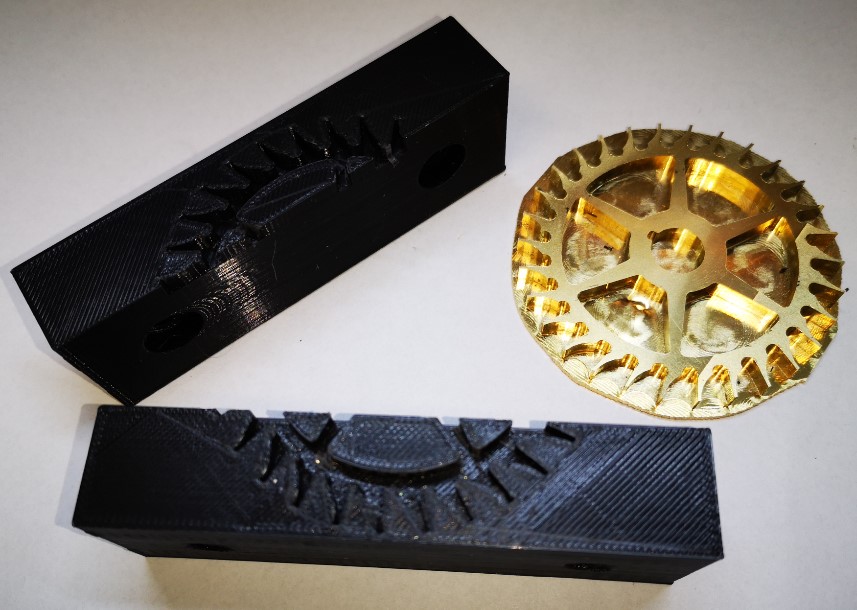
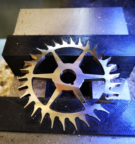
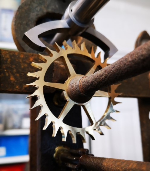
Close up view of the fillet modifications to the projected sharp corners of the wheel outline into the soft jaws.Soft jaws and the brass wheel ready to be skimmed. The residual original square stock has been roughly trimmed around the wheel circumference.The jaws were printed and I have to say were somewhat cosy tight around the wheel geometry. When the jaws were mounted in the machine vice, the wheel was not going anywhere and the excess backing brass was skimmed off quickly and easily with no apparent movement of the wheel in the jaws.Finished wheel mounted in the jaws after the excess work holding stock had been skimmed off.The finished escape wheel and pallets mounted in the Thwaites clock
I am really warming to this technique. It is quick and easy to implement and any mistakes can be quickly rectified with a new 3D print without having to remake aluminium versions. I like it and recommend it.
A comment that I often make is about how having varied resources available to do a job creates on the one hand a quandary as to what route to take but on the other hand it can lead to a light bulb moment. Having a 3D printer available along side a CNC machine often creates this dilemma and often to advantage.
Stick with me on this.
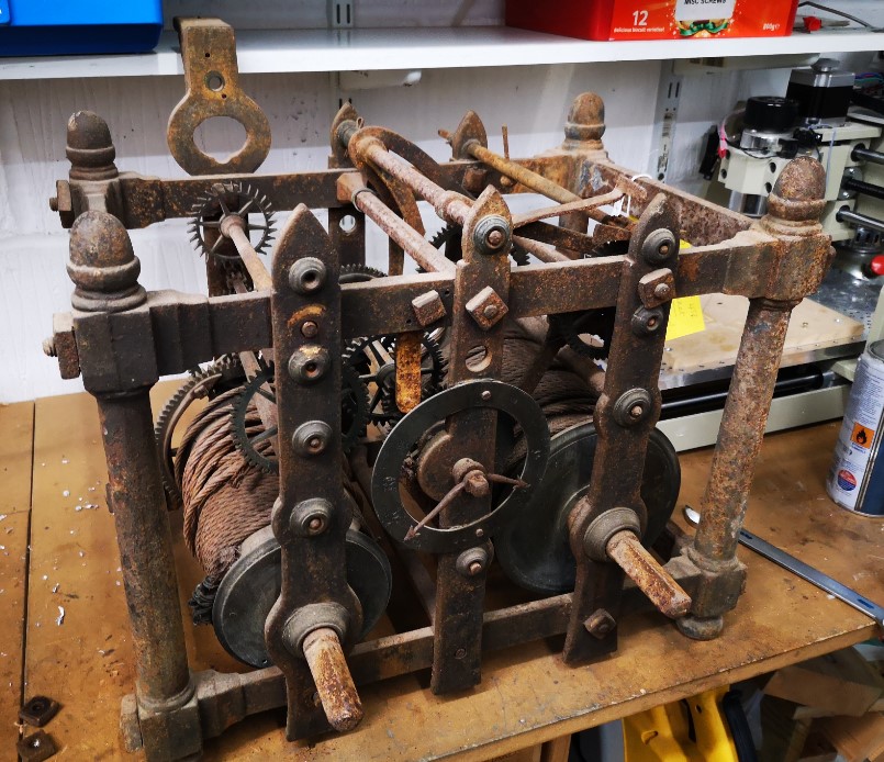
I am currently immersed in creating parts for an old turret (church) clock as pictured below. My wife put it down as a JSN job but once again the challenge it presented won the day.
Not a pretty sight but things do seem to move and things are certainly missing.
The client found me from my blog entry about creating the Brocot wheel in CNC. His clock as you can see is missing the pallet arbor, pallets, crutch and arbor suspension bracket. If that wasn’t enough it also needs a new escape wheel. This is very similar to the aforementioned Brocot wheel but smaller in size. Fortunately the old escape wheel was still in place but in poor shape with the teeth ends fairly battered and one tooth partially missing.
I created the CAM for the new escape wheel in Fusion 360 and then from the wheel design created the geometry for the pallets. (There is a great document created by the BHI as part of their DLC called ‘Drawing Clock and Watch Escapements’ that helped on this as did W.J. Gazeley’s book ‘Clock and Watch Escapements’). In order to check the pallet design I decided to first of all print a 3D model. The printed part looked like it would work when tried against the original battered escape wheel.
Next step in my evolutionary process was to make an aluminium version on the Tormach CNC. I used a superglue mounting block and cut the pallet profile for the full 10mm stock depth and down to the blue mounting masking tape. Because the aluminium was so soft and I kept the DOC gentle this turned out well.
Although the aluminium version worked very well and helped me prove the working of the clock, aluminium is too soft for clock pallets. A steel set would now needed and I opted for 20mm ground flat stock as the ideal material.
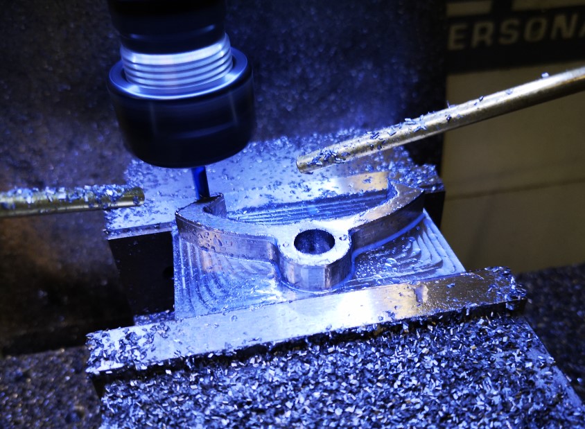
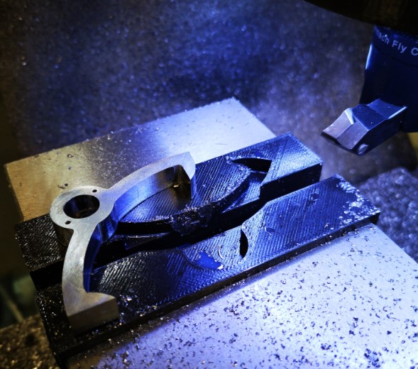
Side #1 was cut while being held in the machine vice on parallels. A 2mm thickness of stock was left as the gripping layer. All went to plan.
Side one machining of the clock pallet. An 8mm 3D Adaptive has completed and a 4mm follow on is now being run to clean up the finish. Note the newly installed second Fogbuster nozzle.Finished side 1 operations and ready to invert to remove the residual stock used to grip in the vice jaws
Side #2 now became the headache. I could have used the super glue bonding of the stock as per the aluminium version. My twitch was that this would leave very little of the pallet material remaining to act as a secure bonding face with the superglue. Given I was cutting steel there was every chance of things parting company. I could hold the model inverted in the vice but there was a real danger of the nib tips getting crushed. Not a good idea.
Clearly the right solution was to make a pair of soft jaws to grip the pallet shape while I was decking off the side #2 residual 2mm.
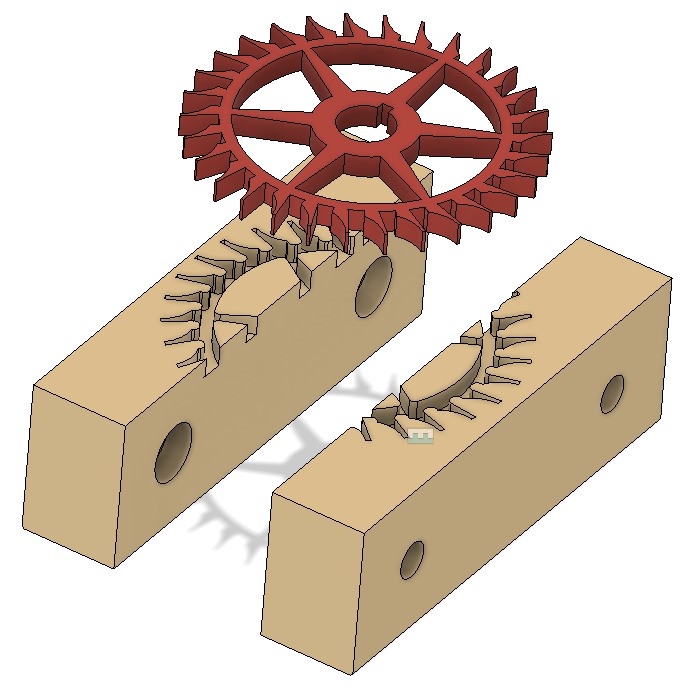
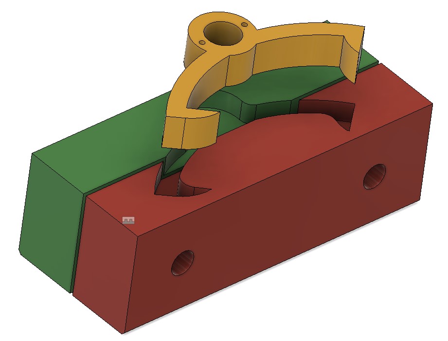
Now here is the light bulb moment. I designed the soft jaws in Fusion so they would swap out the existing steel jaws on my machine vice. This is a straightforward process using the Project function. The best demo of this that I have seen is by Cough42 and is worth a watch.
The jazzed up Fusion view of the soft jaws (red and green) and the finished pallet shape that gets gripped in them.
I was about to order some aluminium stock to make the soft jaws when the 3D printer winked at me from the corner of the workshop. Could I print the soft jaws on the printer and get enough grip to allow the last 2mm to be decked off ? This had to be worth a try and had the advantage that I could be getting on with another of the clock components while they were printing.
Taking this route I decided I would need to modify the design in Fusion. The 3D printer always leaves cavities a bit under size. I used Fusion’s Offset Faces to increase the profile shape by 0.2mm all around. I set the gap between the two jaws at 1mm.
Print time was around 2.5 hours for each each jaw. With CAM and setup time, running them in aluminium would have been similar. I gained the 5 hours to do something else. (i.e. Drink tea watching the mill ….)
The idea worked. The PLA tightly gripped the inverted Side #1 profile while I decked off the 2mm residual stock. I didn’t go too aggressive on DOC.
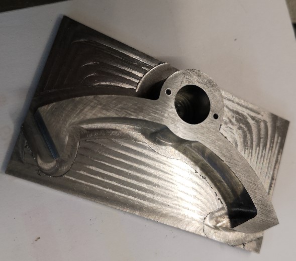
View of the finished pallets with the PLA soft jaws in the background mounted in the machine vice
A set of PLA soft jaws – not a radical idea but food for thought.
Aluminium soft jaws are essential if you are going to be undertaking detailed feature machining of Side #2 but if it is a simple decking skim then PLA would seem more than adequate. Soft jaws are 1 off items dedicated to a particular part. They are consumable as is the PLA but the PLA versions are overall quicker to produce.
This has been another situation where what would have been a no brainer ‘this is how we normally do this’ turned into a ‘how else could I do this with the resources at my disposal and make life easier ? ‘. It is that lazy side of me shining through yet again …..
This is probably not original but worth commenting on. I have a tooling plate on the bed of my Tormach PCNC440. This has a matrix of M8 holes on 25mm spacing together with intermediate 3.7mm tooling pin holes.
Quite often I have a need to set up my work CNC coordinate system (WCS) such that it is centred on one of the M8 holes.
If I want to do a quick and dirty centre on one of these holes then I use the Laser Centring tool as mentioned elsewhere on my blog.
If I need to be a bit more precise then I have a mushroom/top hat shaped disc with shank that is a tight fit in the tapped M8 holes. PathPilot has a number of probing routines and these include finding the centre of a circular object. Simply push the top hat into the desired hole and then probe the disc for centre. You can use an active probe such as the Hallmark ITTP.
If you haven’t got an active probe you can use a Haimer. Simply align the Haimer tip somewhere close to a maximum point on the disc circumference and advance the axis to show a reading on the Haimer. Rock the opposite axis back and forth and watch the Haimer reading to find the high point on the circumference. Zero the axis. Go to the opposite side of the disc and repeat this process and divide the measured diameter by 2 for the disc centre. Repeat on the opposite axis.
(You can use this Haimer rocking back and forth method to find the diameter high point when cross drilling a circular item to fit grub screws etc).
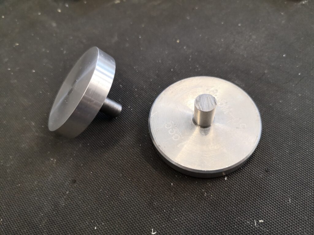
Two examples from my ‘mushroom farm’
The mushrooms are made with a silver steel shank that is skimmed to be a non wobble (how technical is that ..) fit in M8 (~6.8mm) and an aluminium top hat that is superglued in place on the shank. Once the glue has set the top hat is squared up while held in a collet in the lathe. This ensures concentricity with the shank. The disc will now sit flat to the tooling table when the shank is pressed home and perpendicular in the hole.
Clearly the larger the disc diameter the less centring error there will be.
I now have a ‘mushroom farm’ of discs for all manner of hole sizes. It’s not rocket science but as you well know, I am all for a simple (aka lazy) approach. Apologies to all the Grannies out there.