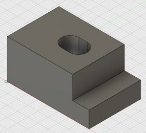
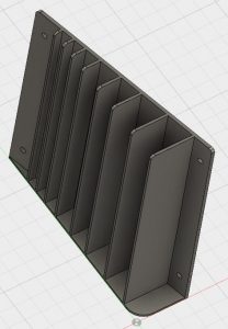
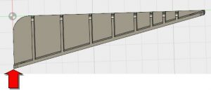
While doing the drawings for the Rosebud grate on Fusion 360 I cheated slightly. From my measurements, I made a best estimate sketch of the needed grate size to fit the firebox floor and having drawn this up, I did a 3D print of an equivalent size thin piece of PLA. Having trial fitted this printed plate I did some trimming on the Fusion drawing ready to create the CAM.
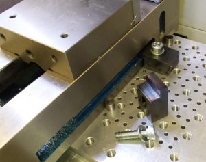
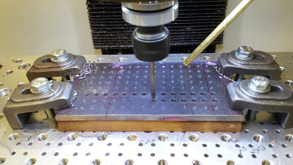
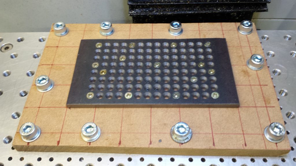
I had bought in some 150mm square black mild steel plate and cut it roughly to width but left the length at 150mm this being longer than needed. This allowed me to clamp the ends of the stock to my tooling plate on a piece of MDF. I had one clean cut edge on the cut stock to use as a reference. When mounted I checked this with the Haimer to make sure it was running parallel in the X plane. Note I cut the MDF to roughly the same size as the plate so as not to interfere with the clamping.
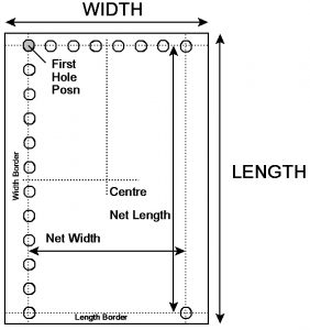
I did a PathPilot width and length measure using the Haimer and found the centre of the plate and set this as G54. My Fusion drawing and CAM were referenced to centre. I was now ready to go.
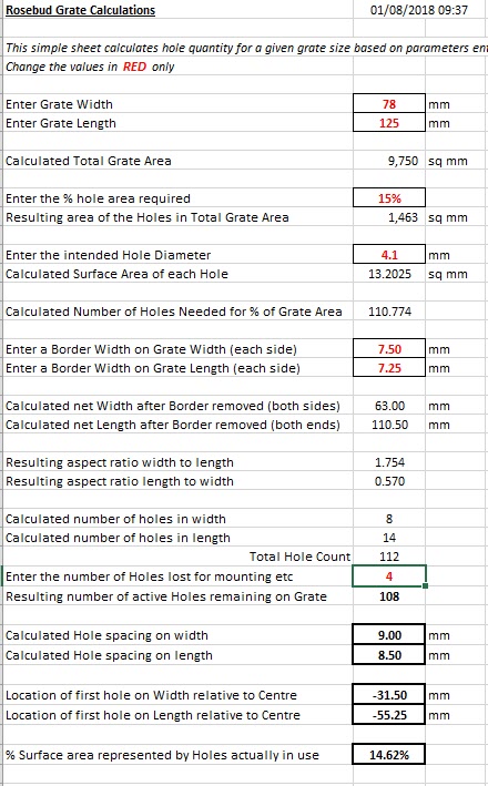
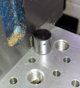
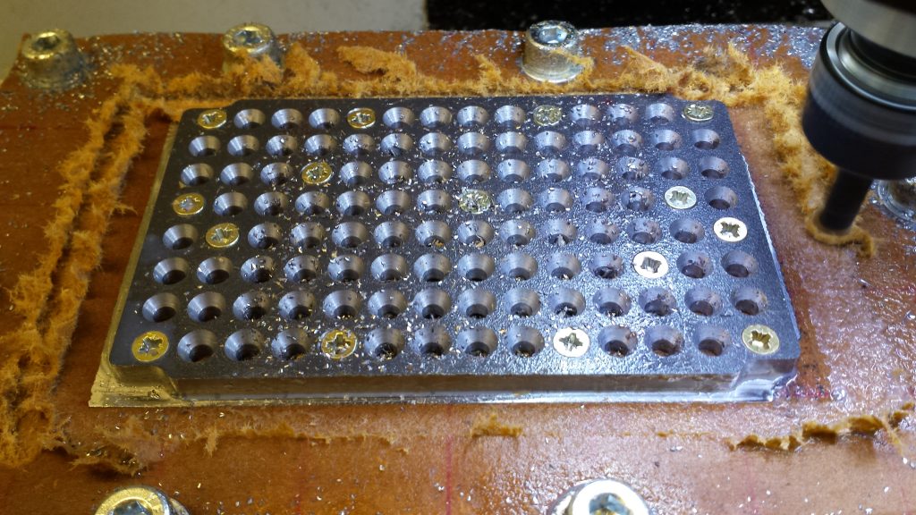
First operation was to spot the matrix of holes and the second op was to drill them out to 4.1mm. Third op was to countersink the holes to 3mm depth. This was a bit interactive. I just worked on one hole only to start with and did repeated cuts using a BS3 countersink until the depth was correct. I then did a ‘chose similar size’ selection in Fusion CAM and then ran the full op.
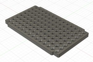
This now left machining of the profile of the plate to the size of the fire box floor dimensions as per the CAM and my dummy PLA plate.
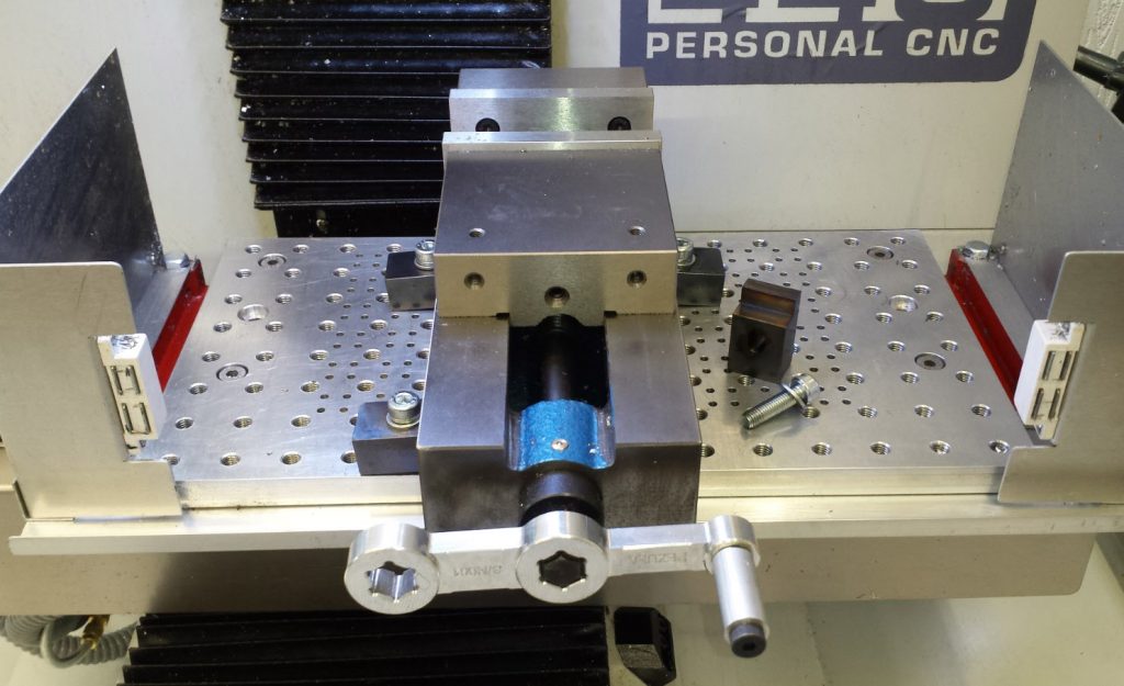
Clearly the clamps were now a problem as the end areas were excess material on the length. To get round this I removed the drilled plate from the MDF (the MDF had already started to degrade and swell with the cutting fluid) and mounted a new piece of MDF on the tooling plate with M8 fixings. As you will see below I went a bit OTT with these …. there is even a hidden countersink one under the plate to stop the MDF bowing upwards …
I remounted the grate on the new MDF with a single woodscrew in one of the grate holes and checked and adjusted the angle of the plate so the good edge was running true in X as before. I then added a ‘sprinkling’ of more wood screws so the plate was firmly in position and running true. I then re-referenced G54 to the centre of the grate as before.
Now I hate making swarf (chips) of material if it is not necessary … so having got the plate securely in place on the MDF I then took it off again and cut off the excess material on each end of the length. Sad really but you never know when you might need a couple of small pieces of steel …
The grate could now be mounted back on the MDF with the plethora of screws positioning it back as before. I did re-check with the Haimer and also rechecked the Z height once again.
The CAM adaptive profiling was with an 8mm cutter. Obviously I was cutting air at each end of the grate where the stock was now missing but not a problem.
I could have used a super glue and masking tape holding method but the black mild steel does not have a smooth surface like BMS and I was doubtful how well it would hold. With hindsight the method I adopted did give me some flexibility in the process method.
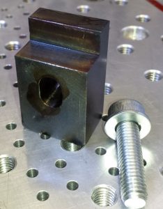
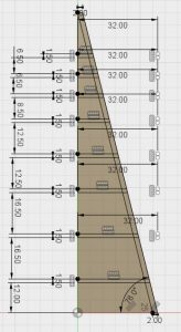
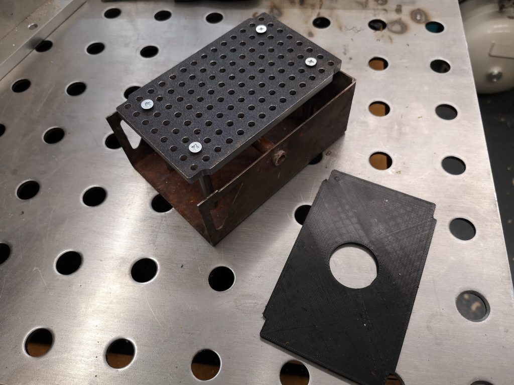
The final process on the Myford Super 7 was to make four posts to sit the grate at the correct height spacing above the ash pan to match the old bar grate position. These posts were fixed onto the grate by sacrificing four of the holes. This of course reduces the hole count and therefore the hole area percentage occupancy from 15.17% to 14.62% – but not worth worrying about.
So now I have to prove that all this effort was worthwhile and the grate will make a difference to the Polly V steaming. More to follow on this in due course. We have had some rain over the past couple of days so the Club track will no doubt be open for steaming in the near future.
Similar or related subjects : –
- Model Railway Track Testing Monitor
- Swiss Vapeur Parc Festival Week
- 3D Printed Jigs to the rescue
- Rosebud Fire Grate on a Silvercrest BR Class 4
- Simple Water Level Sensor for Live Steam Locos
- French Model Steam Engine Gathering
- Replacement Whistle on Polly V Steam Engine
- Bad day steaming with my 5″ Polly V live steam locomotive
- Lempor Nozzle added to Poly V 5″ steam locomotive
- Setting up the timing on a Polly V locomotive