I am slowly getting to understand how to manipulate and use my recently purchased Quorn tool cutter grinder. One frustration that kept cropping up was the workhead assembly slip rotating on the bed bar. This usually happens when there is a need to slide the tool holder head back after a referencing action. This messes up the reference setting.
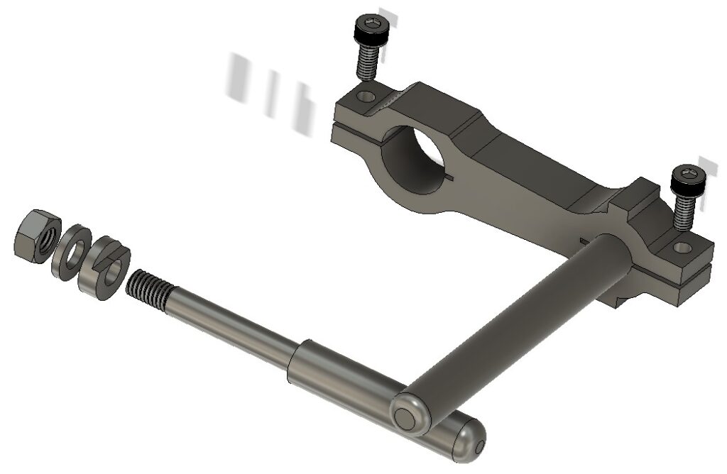
I chanced upon a thread on the MEW forum where a John P had solved this problem with a parallel support bar assembly. This utilised the 1/4″unused hole in the toolholder side wall. There are a number of ways to fabricate this fixture but the important aspects are that it should be robust and must ensure a parallel motion along the support rod.
I opted to model the bracket in Fusion 360. As there will be little stress on the bracket in use I opted to mill it from 15mm cast aluminium to give a 12mm finishing depth. Here is the pictorial view from the Fusion desktop.
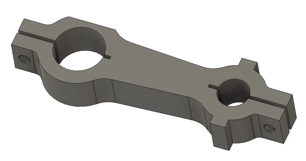
The bracket has a 5/8″ hole to match the Quorn table slider rod and a 10mm hole for the new parallel support rod (sorry about the mixed dimensions but my Quorn is an Imperial model and most of my stock is metric).
Side #1 CAM operations are to clean up skim the stock top surface followed by profiling the two holes and the outside shape. Side #2 is to invert the model and deck the excess material. The clamping slots, the flat adjacent to the 5/8″ hole and the M4 tapped holes are all supressed in the CAM and manually cut post CNC operations.
The model has two tabs adjacent to the 10mm hole. These have no relevance to the use of the bracket but are there to make the width of the model equal. This negates the need to use soft jaws to hold the model when undertaking side 2 operations to deck off the excess stock material. The decking brings the model to 10mm finishing depth. These two tabs could be ground off afterwards if desired.
I did consider grub screw clamping of both bars but there was a danger of deforming the associated bars. It was easier and more elegant to design slot clamps into the Fusion model. The clamping slits were cut post CNC machining on my BK3 bandsaw. (Try cutting straight slots on a BK3 without a decent fence and support bearings.) The parallel nature of the finished model width as mentioned above makes this a simple process against the bandsaw fence.
The two M4 clamping screw holes are drilled prior to the slots being cut. The holes are drilled 3.3mm through and then M4 through threaded. After the slots are cut one half of each hole is clearance drilled to M4.
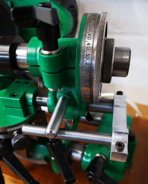
The flat adjacent to the 5/8″ hole is the last ‘after CNC’ machining operation. This flat gives the clearance needed to allow the bracket to slide under the Quorn toolholder referencing dial.
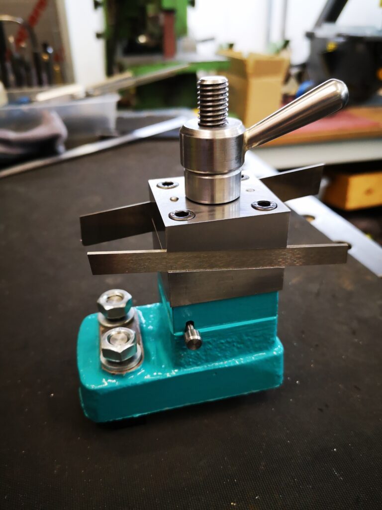
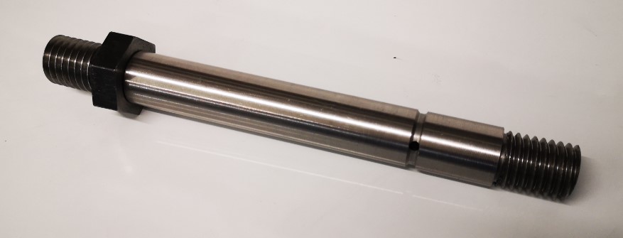
The gliding bar is mounted in the spare hole in the tool holder side wall. This hole in my Quorn had been drilled 1/4″. The rod profile was turned with a centre from 10mm silver steel to have the 1/4″ section and then a short section threaded M6. Note that I also made a brass washer profiled to match the rear face of the through hole in the body. Like most of the Quorn casting holes this had a step segmented surface aimed at stopping bolt head rotations.
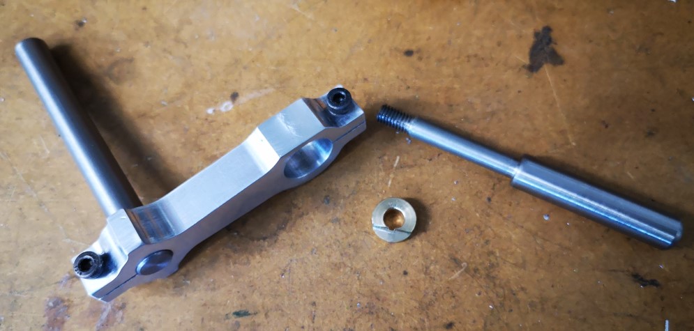
Mounted on the Quorn, the assembly sat nicely parallel, is very solid and stable and does an excellent job of stopping the head drooping. My frustrations over this aspect of the Quorn are eased for the time being.
If any readers want the Fusion file or dimensioned drawings then add a comment below.
UPDATE : – The bracket should be rigid enough when 3D printed instead of machined from solid. Here is a ZIP file containing the support bar clamp version v5 as a STEP file. All the other parts are straightforward lathe operations.
Similar or related subjects : –
- Fanttik super tool is well worth a look
- Small handheld vacuum cleaner
- Eccentric Engineering Turnado freehand turning tool
- Rotring 300 2mm clutch pencil modification
- Kindling Cracker – a safer option
- SINO SDS2MS DRO repair
- A useful Amazon sourced small item storage system
- 3D Printed Threads Modelled in Fusion 360
- Three axis stepper controller PCB in stock
- Myford Super 7 Large Bore depth stop