Using Fusion 360 Parameter Functions on this useful tool
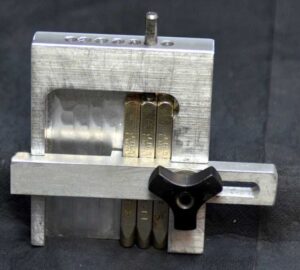
I was pointed to this punch holder idea by a friend. It was shown on HomeMadeTools.net and conceived by Andy Foale.
Here is the link to the original post : –
https://www.homemadetools.net/forum/multiple-hand-stamp-helping-hand-65882
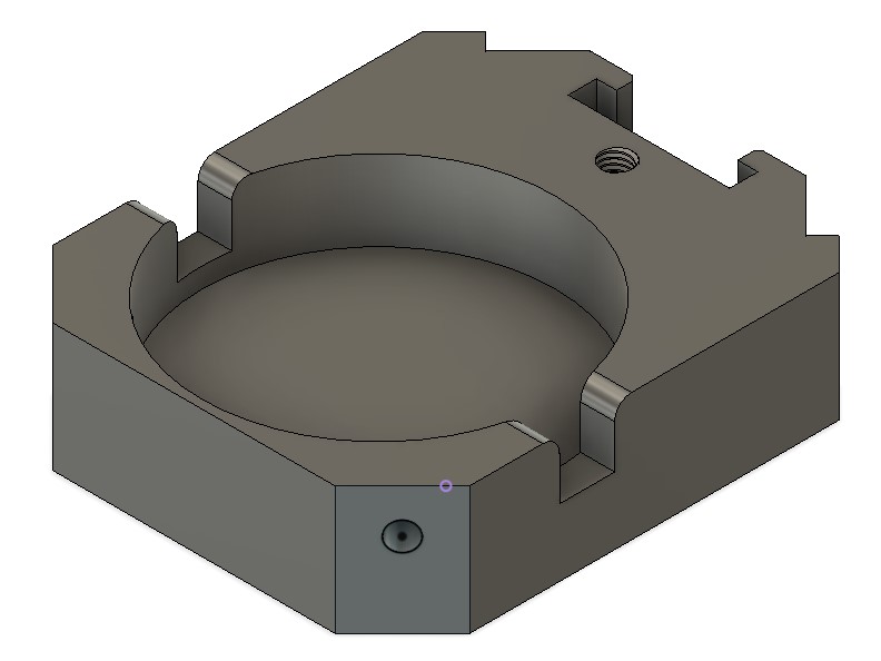
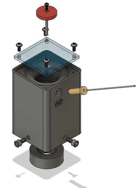
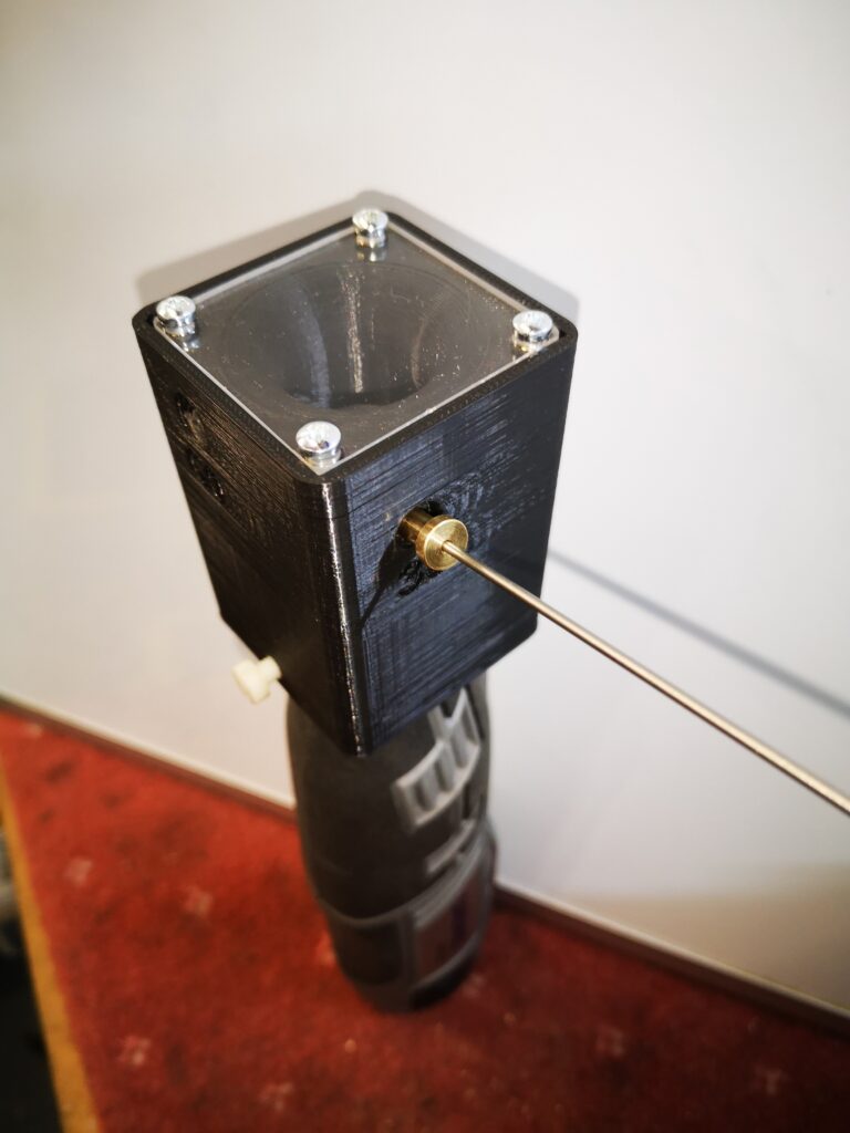
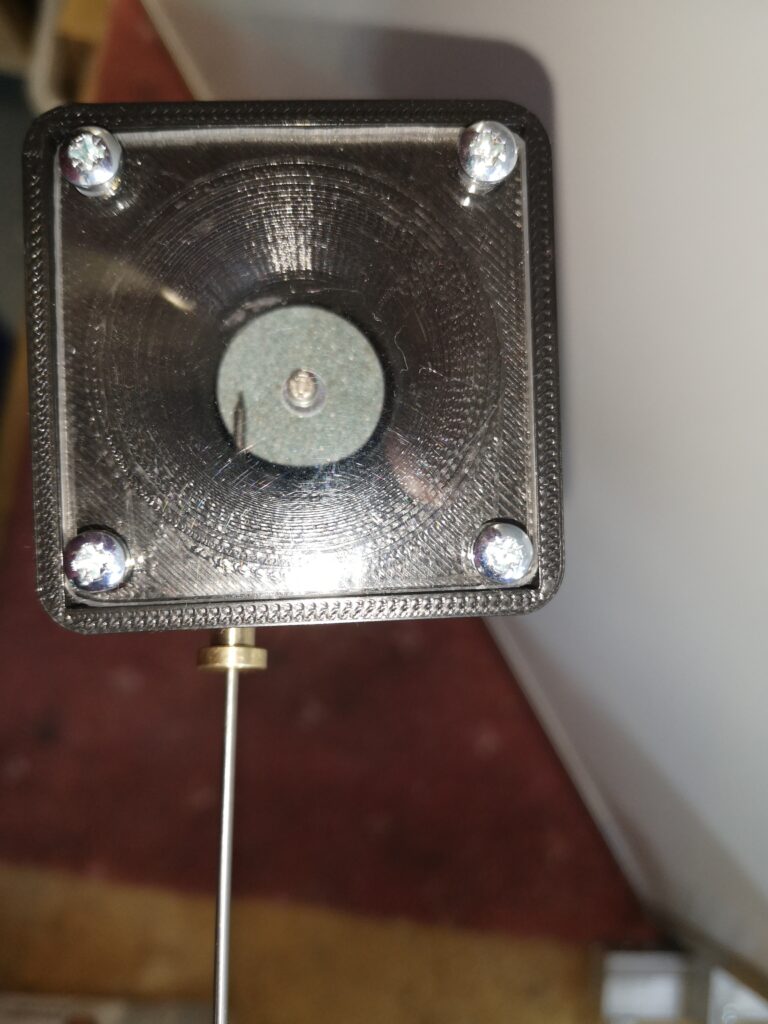
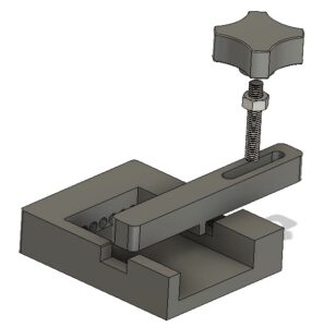
I thought it might be practical to make it as a 3D printed device and with a bit of guesswork came up with a first pass design in Fusion 360. This was based on my set of punches which are 6.4mm square (1/4″) and 58mm long. The design printed in PLA without any problems and the finished punch holder worked fine. It uses one of my printed knobs as mentioned in another post.
The success led to requests from others who liked the 3D print concept but had different size punches so needed the design tweaked to suit.
This looked like a good excuse to re-familiarise myself with Fusion 360s Parameter functions. In short these allow you to program interrelated dimensions in a design through a series of basic algebraic functions. The end result is a design that is fully flexible on the size of the punches to be used and the number of punches that might be judged needed as the maximum ‘word’ length.
The Fusion file is here in a ZIP file
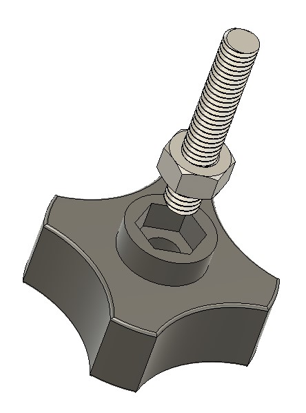
The Fusion file includes the holder, the clamping bar and the knob body. You will need a short length of M6 threaded rod and a M6 nut to finish the knob. The file is configured to 6mm punches, 63mm long but you can edit using Parameters function under Modify. Clearly once you have the Fusion file you could run also run a CAM program and CNC cut the punch holder.
I am afraid this is a Fusion 360 file only. If you aren’t a Fusion user (why not ??) and you want a STEP file creating to your punch sizes then email me and I can run it for you.
As stated in the original article, the kerning of the letters is defined by the punch cross section.
Similar or related subjects : –
- Hybrid 3D brass threaded insert tool
- Tap shank adapter for 4mm AF hex drivers
- Qidi Slicer auto support error on my part
- Qidi X Smart 3 revised fan installation
- Qidi X Smart 3 tweaks
- Qidi X Smart 3 special weekend pricing
- Stop losing Qidi ifast 3D prints down the chamber front gap
- Fitting a Bento air filter to a Qidi ifast 3D printer
- 3D Printed Brass Threaded Insert Soldering Iron Stand
- eSUN filament reel silica drying pod