The Rosebud Phenomenon
I recently had a discussion with a fellow model club member about fitting a Rosebud grate to a Polly V locomotive. There is quite a lot of discussion on various forums of this style of grate so I won’t repeat what has already appeared in the likes of Model Engineer. The gist of the design is to replace conventional live steam bar type grates with a plate having a matrix of holes with back countersinks such as to occupy around 15% of the grate area. The effect of this change is to get better combustion of the fuel and better efficiency. Most users report only a fine powder residue after steaming and have observed that the fire appears to ‘float’ on the plate surface. The back side countersinks appear to create a sort of Venturi effect to boost the draught to the fire.
How to Calculate the 15% matrix
So all this got me thinking. This would be an easy job to run on the Tormach and all I needed was the design entering on Fusion 360. Which brought me round to the calculation of the 15% surface area for the holes on the new rosebud plate. Those who know me will bear witness to my weakness for doing spreadsheets and this little problem suggested a spreadsheet was needed.
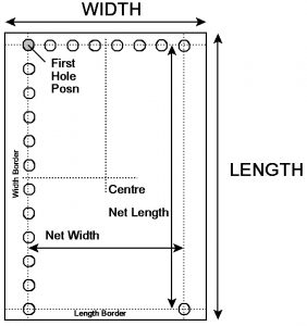
Below is a simple sketch of a rosebud fire grate with dimensional attributes. In the calculation I have allowed for a border around the holes in case there are any no-go areas for the hole matrix. I have now updated the spreadsheet to allow holes to be ignored such as where used for mounting pillars. I also give the XY coordinate of the corner holes relative to material centre to help the machining layout.
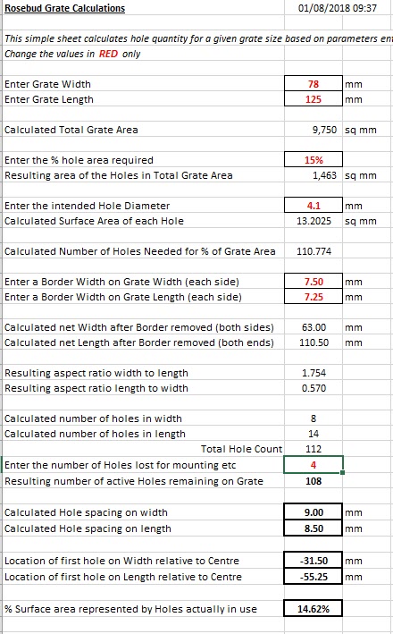
Below is a screen shot of the resulting rosebud grate spreadsheet and you can download it as a ZIP file via the following link – rosebud_grate_calculator 2
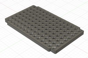
Here is the finished Fusion 360 drawing ready to run on the Tormach. This shows the bottom surface with the 4mm through holes having been half depth countersunk. Clearly four of these holes will need to be sacrificed for mounting legs onto the locomotive ash pan and these are removed from the above calculation.
So all is in place ready to cut metal and I will keep you posted on the progress and steaming results in due course. (There is a slight problem at the moment in that we have a steaming ban in place because of all the dry vegetation at the club track).
Similar or related subjects : –
- Model Railway Track Testing Monitor
- Swiss Vapeur Parc Festival Week
- 3D Printed Jigs to the rescue
- Rosebud Fire Grate on a Silvercrest BR Class 4
- Simple Water Level Sensor for Live Steam Locos
- French Model Steam Engine Gathering
- Replacement Whistle on Polly V Steam Engine
- Bad day steaming with my 5″ Polly V live steam locomotive
- Lempor Nozzle added to Poly V 5″ steam locomotive
- Setting up the timing on a Polly V locomotive