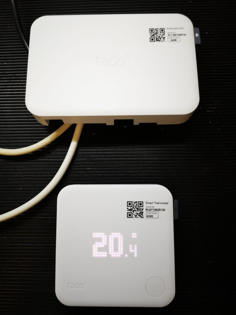
Some time ago I saw an advert offering a big discount on a SDS Rotary Hammer drill from a local tool store. I had no idea what a SDS drill was but one of my associates convinced me it was a good deal and worth getting. Looking like a weapon out of Star Wars, it has since sat under the bench in its carrying case and never used …. until today …..
SDS Rotary Hammer Drill
I had to fasten a new garden hose to the external wall through an outer cement facing and into brick. Normally if I can see the mortar between the bricks I cheat and fasten into the mortar. Today however I could not see what was behind the facing cement and the hammer setting on my normal hand drill was making no impression. Light bulb moment …. let’s try out that SDS.
The wall could have been made of cheese such was the speed that the holes were cut. Lovely machine. If you haven’t got one – get yourself a SDS !
After I decided to buy a Tormach milling machine I had debate whether to go for the 440 or the 770. This confusion was based on available workshop space and to a lesser extent on cost. I also did not have a feel for the total cost of not just the items I needed to buy but also what the total package would cost when it landed on my driveway. In the UK we pay VAT on not just the goods but also the delivery cost.
To help my thinking I put together a spreadsheet on Excel that split out the basic machine parts and then had a common section showing all the accessories I would need. This totaled everything up in USD and I then did a conversion to GBP at spot rate and then added VAT and duty factors for UK import.
This sheet helped my enormously and once I had all the key prices loaded from the Tormach site I could do ‘what if’ calculations to fit my budget.
I was recently contacted by another potential buyer of a Tormach and I sent him the sheet to help his thinking process. For anyone else thinking of buying either in the US or an overseas country I thought the sheet might help so I have spent some time cleaning it up and and I attach the new version below.
Simply put a quantity of each item in the column associated and see the impact of your shopping list at the bottom, either as a 440 or a 770. Clearly the sheet could be extended to a 1100 if that takes your fancy. (Don’t forget to check the current pricing from the Tormach site by searching on the product code shown on the sheet).
I know it has been quiet for a couple of weeks but we took a holiday to get some sunshine, some golf, some snorkeling, some eating and sleeping. Much enjoyed but I am starting to twitch now and need to get back into the workshop. Still it has given me time to think about the next project and I have had time to book for the NYC CNC Open House in Chicago in September.
I got a Dell XPS13 from EuroPC just before we left home which I have been playing with under the guise of sitting ‘relaxing’ on a lounger. I am impressed with it as a machine. Nice screen, decent battery life and quick to boot. It came with Win10 Pro which I had never ventured into and while it has some nice touches I still prefer Win 7. I managed to download all the apps I needed at the airport lounge before we left (including Fusion …) so it has been fun to play but you need a real job to do in order for things to sink in and to learn. Incidentally I did a speed test at the airport and was staggered to see 100Mbps download and upload speeds with a few ms ping time so clearly on fibre.
I also downloaded a load of books onto the Kindle to keep me occupied and was impressed by Los Alamos by Joseph Kanon which is a ‘who done it’ woven around the Manhattan Project. This lead me to Wiki to refresh me on the background on Trinity etc. Incredible engineering and if I have my dates correct, no CNC systems to manufacture the parts.
After a few distractions the Mill Turning Jigs are complete and I have run a test piece that is representative of a clock pillar.
Mill Turning Jigs
The jigs were both designed in Fusion 360. One consists of a large block with space for three 10mm cross section carbide insert tools and a second block with drill and boring related tools. I have fitted three ER16 collet chucks to this to allow flexibility of tooling choice. Both have mountings to fit onto my 25mm hole matrix tooling plate on the Tormach.
The jig manufacture was relatively straightforward with the exception of needing a new 10mm end mill having extended length (35mm) to bottom out the ER16 collet mounting holes. I got this from APT and the edges were lethally sharp.
I opted to base this on the largest pillar I had come across in any design which was formed on a 5/8″ brass rod. I held the stock in the spindle in a 16mm ER32 collet held in a TTS holder.
I struggled a bit with the CAM for the trial as the tool geometry of the tools I recently received from Banggood were not in the standard tool library. I got some of the settings wrong. That aside the result of the first run is quite pleasing.
My feeds and speeds were a bit coarse and I cringed once or twice at the tortured sound of brass under pressure. I didn’t complete the parting off as I didn’t fancy ducking from a large piece of brass spinning lose at 5000 RPM.
Mill Turning Setup showing both Jigs in placeZoomed view of Trial Cuts
As ever there was quite a bit of learning while making both the jigs and running the trial pillar test piece.
As part of my purchase package of the Tormach PCNC440 I ordered their granite block and height caliper. This meant I could measure and set tool heights directly into the tool table on PathPilot via the caliper USB connection. See the image below which shows the granite block, caliper and the associated dongle box.
This concept works really well and saves manual entry typo errors when measuring tool lengths. I have found one problem however and that is the caliper eats batteries at an alarming rate. These are CR2032 button cells which are not dramatically expensive, but the cost does start to add up. There is the added frustration of the caliper potentially not functioning at a critical moment when a new tool needs to be measured.
It struck me as strange that a device talking via USB should be dependent on a battery when 5V is available from the USB interface. The fact that this did not happen suggested to me that the connection from the interface box to the caliper did not have through continuity of the 5V supply. This wasn’t surprising given that the caliper runs from a 3V cell.
Investigation
I connected the caliper via a standard USB cable directly to a variable power supply connected onto the 5V power pin on the USB cable. Varying the power supply from 0V to 5V showed that the caliper would work quite reliably over a range of 3V to 3.8V but above this the display would blank or just show 8888 at high intensity so masking the actual reading.
I found a couple of 1N4148 signal diodes in my component stock and put them in series with the 5V feed from the power supply to act as a series voltage drop. This brought the working voltage delivered to the caliper back into the 3V to 3.8V range where it functioned without any problems.
Implementation
So the question was now as to how to implement this modification elegantly ? ….
Be warned that the modification to be described involves a change to the USB dongle box supplied with the caliper and as such will invalidate any warranty. Mimic what I did at your own risk.
The dongle box has four screws on the bottom cover and removing these reveals the controller pcb. Take care not to loose the three blue switch activator rods in the process. On inspection of the pcb, the USB cable entering the box has all four standard USB connections but the cable exiting to the caliper has the 5V lead (red) disconnected.
I found a pin quite close by to the output lead that was marked 5V. This was a possible feed for my two diodes. On measuring this I found it was at a lower voltage than expected suggesting that there was perhaps some circuitry between this point and the incoming 5V. I therefore chose to ignore this and looked instead to the input connection cable. I found the +5V connection (red) as it connected to the pcb. I connected the two diodes in series to this cable termination and then ran a connecting wire (orange below)across the board to the 5V output (red) cable which was previously not connected.
These modifications are shown below albeit with hot glue over the diodes and connections.
Modification to Tormach digital caliper dongle box
This completed the modification. I checked out all the voltages while the pcb was still outside the box and also checked the caliper was still working. I replaced the pcb back into the box and screwed the lid in place.
One final thing I did which is not necessarily essential but felt like a good thing to do, was to put a tantalum capacitor across the former battery contacts in the caliper battery compartment. This would act as decoupling should there be any ripple on the new supply to the caliper. See the image below. Note that the tantalum capacitor is polarised and its + lead goes to the former + battery contact (on the right as shown below).
While this is a potentially useful thing to do, it has the disadvantage that you cannot put a battery in the caliper if you want to use it ‘off line’ when not connected to a USB port. You could however plug it into USB charger via the dongle lead.
The other minor thing I did was to fit a small cable tie to retain the caliper connector in place as I found it easily become disconnected.
On putting the setup all back together, the caliper was working well with a nice contrast to the LCD display. Tool table updates work just as they did before so no issues there.
If you do this modification you might want to experiment with different diodes or the number of diodes needed to the drop the voltage from 5V to within the caliper normal voltage range. Note that you need to use small signal silicon diodes which will have around a 0.6V voltage drop per diode. Don’t use Schottky diodes as these generally have around 0.2V and so you would need at least 3 times as many to achieve the same overall voltage drop. You could try LEDs as they all seem to have different voltage drops but they tend to need a high drive current which if this is the case, makes them unsuitable for this application.
You could of course go really elegant and build a small integrated power supply chip into the dongle box such as the AMS1117. These are available in various fixed output voltages including a 3.3V version (which is popular for Arduino projects and available from Amazon). You can also buy a ready made 5V to 3V module based on the AMS1117 from Amazon. I like the AMS1117 and used the 1.5V version in my power supply modification to the Shumatech DRO systems.
Here is a printer friendly (and slightly updated) version of this article : –