Tormach provide a rather nice tooling system for their milling machines. This is known as the TTS. There is a master collet permanently fitted in the spindle. If you have the automatic tool changer option fitted this collet is depressed by a compressed air driven ram. This opens its jaws to allow grabbing of individual sub collets holding the tool of choice.
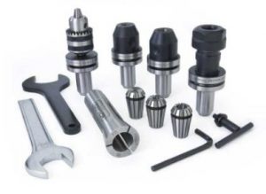
The great bonus of this system is that you can have all your regular (and not so regular) tools permanently mounted in collets ready to go. Press the button driving the ram and push the next tool home. This also means you can populate the tool table in the PathPilot CNC driver program with all the tool length offsets without having to measure each time you do a setup.
It does mean quite an investment in the sub collets. These are available for all manner of capacities both metric and imperial either with fixed diameter grips or standard ER ranges. There are also custom tools such as the Super Fly and Shear Hog plus fittings to take a Haimer shank.
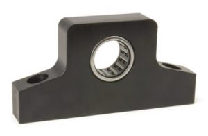
What was always a fiddly job was mounting a new tool in a collet and trying to contra-rotate the collet tightening nut while holding the body. This is now no more ….. I have just taken delivery of Tormach’s simple but elegant solution to this.
It is a ball race mounted in a block but a ball race that only rotates in one direction. You simply push the collet shank into the ball race and it is gripped tight. To loosen the collet you simply put it in from the other side. Magic !
Now you have probably realised I am a bit OCD and like things in their place and ordered. Having got the tool gripping sorted I would now need two spanners to fit the collets of my most popular ER16 and ER20 nuts. That was one too many spanners for my liking and was tying up standard shop spanners (which also have their allocated place in the shop …. oh dear how sad is that).
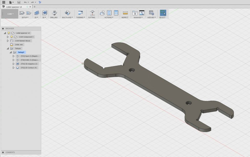
Now I happened to have a strip of 50mm wide Ground Flat Stock sat idle and Fusion 360 was calling. A quick drawing on Fusion delivered a customised spanner sized to suit the two most popular sizes of collet I use. I ran the CAM and off to the 440.
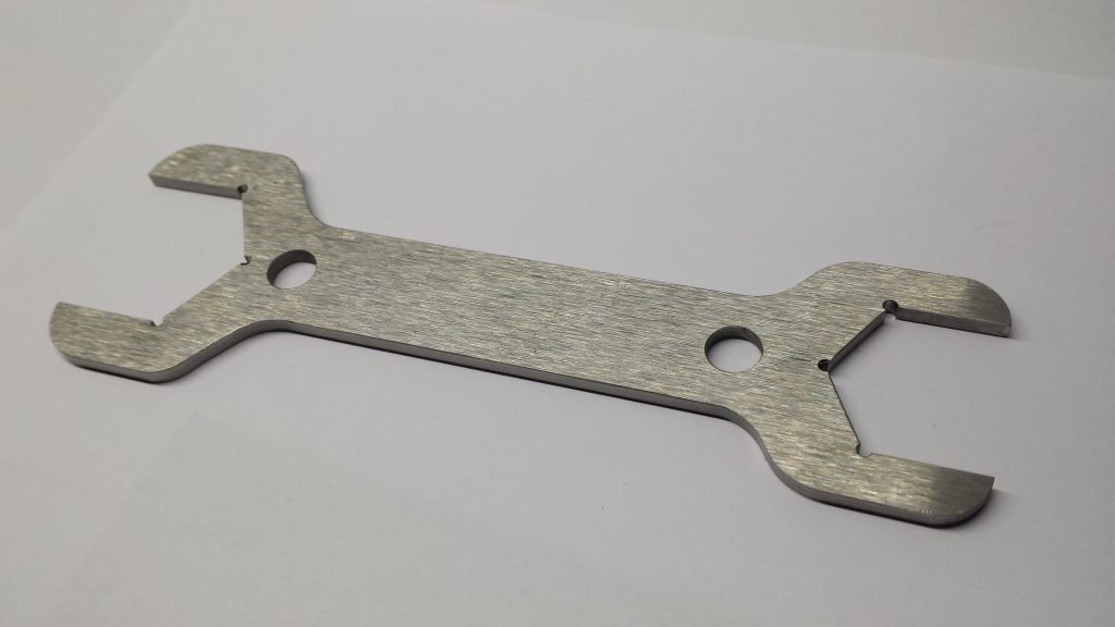
I put a piece 6mm hardboard on top of my tooling plate and put a couple of M8 holes at 75mm spacing on the centre line of the stock and fastened it down through the hardboard into the tooling plate on the 440 bed. I made sure the Z clearance was OK for the screw heads (important !) and hit go.
It was the first time I had machined GFS and the 440 handled it well. I now have a nice customised spanner hanging on the wall above that fancy bearing block.
Disclaimer : – This post and many others on my website feature references to Tormach and its products. I have no connection to Tormach Inc financially, commercially or otherwise. I acknowledge that Tormach®, Tormach Tooling System®, TTS® and PathPilot® are all registered trade marks of Tormach Inc.
Similar or related subjects : –
- Notepad ++ for GCode Editing
- Local power USB switching circuit
- Tormach PCNC440 X Axis limit switch repair
- Experiences CNC machining Aluminium Composite Material (ACM)
- Enclosure finally added to my Tormach PCNC440
- CNC Work Reference Centring using Mushrooms
- Clough42 Electronic Leadscrew Project Implementation Notes
- Floating pressure foot for the CNCEST3040T mini milling machine
- Probes and Haimer Taster Modification
- Arc and Circle I and J code calculator for GCode cutting paths