A simple solution for holding a soldering iron when inserting brass threaded inserts into 3D printed items
NOTE – This is a revised posting with a modified write up.
When faced with adding threaded holes into 3D models I am faced with three choices.
The easy option is to model the threads in Fusion 360. This is fine for a ‘fit and forget’ single fastening but for repeated screw insertion and removal the modelled thread will begin to wear.
My preferred solution is to use embedded nuts in the plastic or leave an open hex cavity to fit a nut into after printing. Some jobs do not have enough space to use the embedded nut technique so brass inserts are the next choice. Brass threaded inserts come in a number of sizes and geometries and are available from Amazon and other sources. The inserts are melted into the printed medium with a soldering iron or other such heat source.
Having had mixed success with a handheld iron I pondered for a while with Fusion 360 whether I could make a jig to improve insertion repeatability. This led to some internet searching and finding a couple of solutions. The first one was via Clough42. He showed a heavily engineered solution supplied by Naomi Wu.
Naomi’s product was impressive but seemed to be way over the top. Next up was a site by Valera Perinski. His site is remarkable and oozes all manner of 3D printed objects, one of which was just what I was looking for – a simple insert punch.
https://www.myminifactory.com/object/3d-print-stand-press-2-in-1-80752
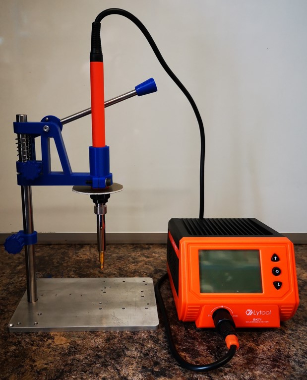
Valera’s design, while simple, looked elegantly functional. I downloaded the STLs. Valera offers these free of charge with a comment that he would appreciate any contributions. A contribution was duly made. Thank you Valera !
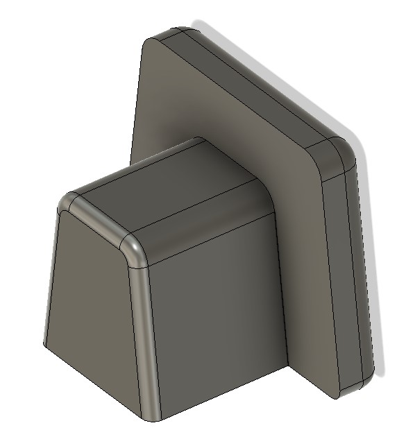
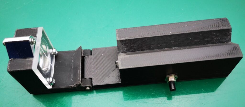
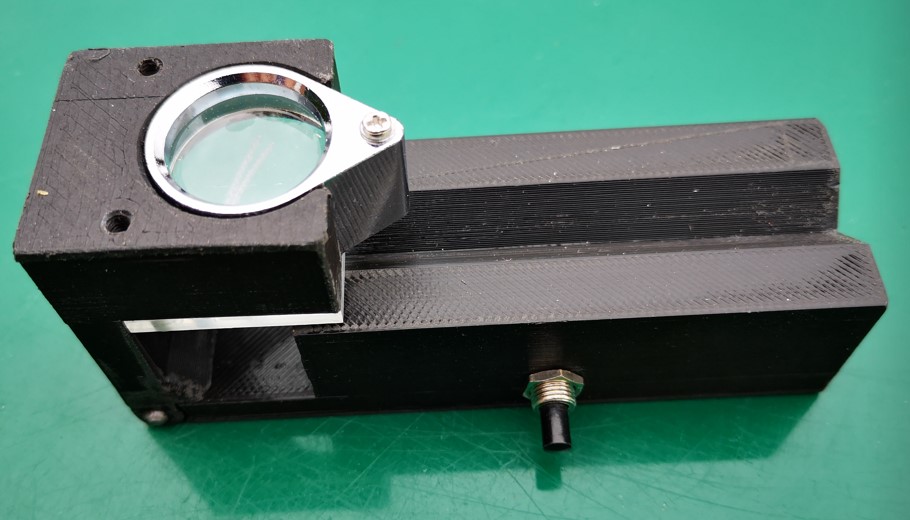
My modified version of Valera’s design is shown above and is described in the attached ZIP file along with the my versions of the 3D print STLs.
Links to similar or related post are listed below : –
- Hybrid 3D brass threaded insert tool
- Tap shank adapter for 4mm AF hex drivers
- Qidi Slicer auto support error on my part
- Qidi X Smart 3 revised fan installation
- Qidi X Smart 3 tweaks
- Qidi X Smart 3 special weekend pricing
- Stop losing Qidi ifast 3D prints down the chamber front gap
- Fitting a Bento air filter to a Qidi ifast 3D printer
- 3D Printed Brass Threaded Insert Soldering Iron Stand
- eSUN filament reel silica drying pod