

I have never been over the moon comfortable with the manual slideway oiler as supplied with my Tormach PCNC440. It has a hand pump that you pump once or twice and this fills a cylinder with oil. Inside the cylinder is a piston that empties the cylinder under pressure from a compressed spring. There are two O rings, one on the piston and one on the cylinder access end cap.
In the course of my ownership of the 440 I have had to replace the O ring on the cylinder a number of times. Once replaced the device works for a limited time and then fails again. The problem is made worse in that I can never find the right size O rings in the UK and have to resort to replacements from Tormach. These are not expensive but when added to carriage costs from the US it does become an issue.
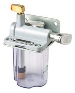
In frustration at the latest failure I found and bought in an alternative manual pump on Amazon. The action is slightly different in that pulling the pump handle action generates the pressure to feed the oil rather than leaving it to the spring return action. When the handle is released, the cylinder refills itself.

Physically the replacement device is slightly larger and I needed to make an adapter plate to fit it in the same position on the rear of the 440. The new device also has twin output feeds. This allowed me to replace the existing T splitter assembly with two separate feeds – one to the X and Y oil distribution manifold and one to the Z manifold.
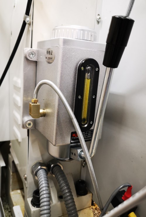
So far so good and it seems to push the oil out to all oiling points. Clearly this is something that has to be monitored or there is the danger of dry slideways and dry ball screws damaging the mill operation. I will report how the new style oiler performs longer term.
It has got me thinking that maybe using an Arduino I could create a ‘time to pump’ prompt beep at switch on and say after 4 hours of operation … a rainy day job ?
Similar or related subjects : –
- Fanttik super tool is well worth a look
- Small handheld vacuum cleaner
- Eccentric Engineering Turnado freehand turning tool
- Rotring 300 2mm clutch pencil modification
- Kindling Cracker – a safer option
- SINO SDS2MS DRO repair
- A useful Amazon sourced small item storage system
- 3D Printed Threads Modelled in Fusion 360
- Three axis stepper controller PCB in stock
- Myford Super 7 Large Bore depth stop
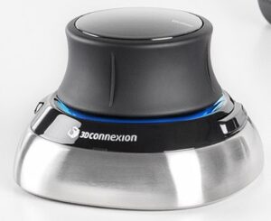 It is supplied with a soft storage pouch and there is a training course app with it which is straightforward. You can then play a quiz to see how good your hand / eye coordination is. Perhaps it is not good to dwell on the results of this ….
Initially it is certainly weird to use but then it seems to click (?) with brain and muscle memory and then becomes a major step forward when using Fusion 360. You use your left hand on the Spacemouse and the right hand for normal mouse activity.
I like it. In fact I like it a lot and wonder why I hadn’t latched onto it before now.
Hopefully it will ease the strain on my right wrist and probably pass the burden to my left wrist …. arthritis rules.
Similar or related subjects : –
It is supplied with a soft storage pouch and there is a training course app with it which is straightforward. You can then play a quiz to see how good your hand / eye coordination is. Perhaps it is not good to dwell on the results of this ….
Initially it is certainly weird to use but then it seems to click (?) with brain and muscle memory and then becomes a major step forward when using Fusion 360. You use your left hand on the Spacemouse and the right hand for normal mouse activity.
I like it. In fact I like it a lot and wonder why I hadn’t latched onto it before now.
Hopefully it will ease the strain on my right wrist and probably pass the burden to my left wrist …. arthritis rules.
Similar or related subjects : –