Tormach’s PathPilot CNC control software offers a Tool Table facility that will accept up to 1000 different tool entries. This is more than enough tools for the small machine shop and if fully populated would represent a small fortune in tools and collet investment.
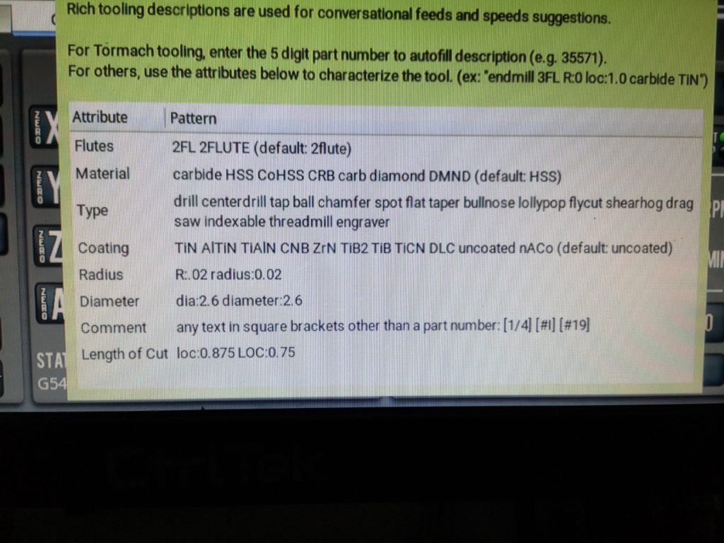
In PathPilot when you go to the Offsets tab to edit a tool, the following dialogue box comes up (sorry about the quality of the image ..) suggesting that you can be quite clever with the descriptions of your tools.
How you describe the tool helps local machining settings such as Conversational routines. It has no impact if you are loading an externally created GCode from CAD/CAM packages such as Fusion 360.
When I first started using PathPilot I had never bothered to add this intelligence when I described the tool. I simply wrote something that meant something to me. As time has passed and I have added more and more tools, the prospect of going back into the Tool Table and making edits to conform to these intelligent descriptions did not seem like a glamorous prospect, even for a rainy day job.
Tormach Changes
What has changed is that in the latest versions of PathPilot, Tormach has added a search routine for the tool table. This depends for its success in finding what you are searching for on the consistency of entries in each line description.
There is now an incentive to have a ‘rainy day’ session and clean up the table entries.
See Mill-tool-table-editor to download a folder containing the description of how to do this and also the Excel file used to manipulate the data.
I am quite anal in needing to have a tidy workshop with everything having a place where I can find it easily. It is a kind of insurance policy to perhaps give me a bit longer time in the workshop before I lose the plot altogether. (The less palatable advantage is the dealer who comes in to clear my workshop when I am in turn in ‘a box’ can easily see what a treasure trove he has stumbled on. We’ll move swiftly on from that thought).
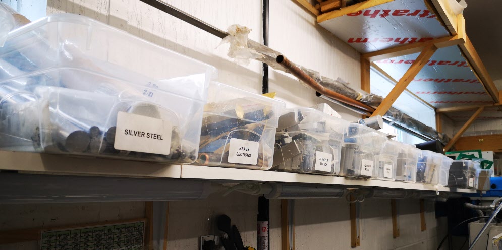
To this end I have settled on using 5 Litre Spacemaster storage boxes for all my ‘stuff’ (technical term as defined by my long suffering wife). These are readily available in the UK at Dunelm and on the net. They are made from a very durable plastic and supplied with a lid which is rarely useful for my application. I believe they are principally intended for ladies to store their shoes in.
Update : – Dunelm no longer supply Spacemaster boxes but Zoro UK have added them to their range. Their stock code is ZT1053092X.
The boxes have a 6.5″x 12″ footprint and are 4″ deep. It is surprising just how much workshop kit can be stored in these (and of course nicely labelled). The 12″ is just not long enough for 13″ silver steel but a little hang over can be tolerated for such useful material.
How sad is this ? Just a small section of my anal storage system
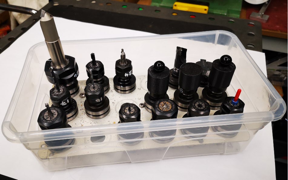
I have accumulated a reasonable (by my standard) set of Tormach TTS tooling collets with my preferred tools permanently fitted. These are each numbered to match my tool table entries in PathPilot. The numbering is done using an Edding 750 white paint marker.
My solution to storing the collets was to use the same boxes. I used a sheet of Dural (150mm x 290mm) and punched a (3 x 6) matrix of 20mm holes into it to take the collets. The Dural sheet sits on 5 off 10mm diameter x 36mm long spacers.
Spacemaster 5L box used for TTS tooling storage. Side view showing Dural plate
To give you some idea of the strength of the boxes, you can pick up one of these fully loaded with tools by the front wall and your wrist will break before the box does. (Well you know what I mean).
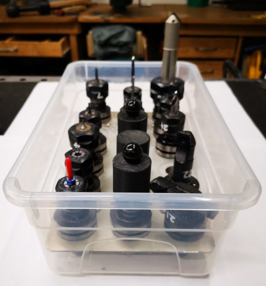
You will notice in the above photo that after some expensive clumsy breakages I now fit 3D printed caps over the most fragile tools such as carbide PCB drills.
Spacemaster based TTS storage box showing protective 3D printed caps over fragile tools
So a bit of a slow news day but thought this might stir an organisational initiative somewhere ……
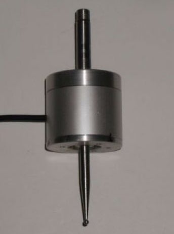
I bought one of the Wildhorse Innovations Passive Probes some time ago and it gets used occasionally (usually when I have dispatched another Haimer tip to happier hunting grounds).
The Passive Probe as supplied by Wildhorse Innovations
The Wildhorse design is nice and simple and it can be bought with a ‘Tormach Option’ which is a cable with a ready fitted 5 pin DIN that is pre-wired to plug straight into the Tormach 440 accessories socket. I have to say it did not talk to the Tormach PathPilot interface immediately. I had to snipped the pull up resistor inside the unit to solve this. When in use on the Tormach you have to designate the probe as Tool 99 in the tool table so as to be able to utilise the PathPilot probing routines (which are very good).
So where is all this going ? Well it is a A to B to C progression …
I dusted the probe off to use the other day and as I had not used it for some time, I did a centring calibration of the probe ball point while mounted in the Tormach spindle. This is a real pain to do as the three centralising adjustment screws are on the bottom face of the body. As a result you can’t see what you are doing and there is a danger of knocking your dial gauge in the process and having to start again.
This got me thinking about whether I could do this adjustment off line in the lathe. This way the adjustment screws on the bottom face are readily accessible. This seemed like a good idea except the umbilical cable is permanently wired into the unit so it needed to be protected from a disastrous wrap round the chuck. Initially I wrapped the cable around the body of the probe and held it there with masking tape but it wasn’t ideal.
Watching the probe spin in the lathe chuck made me also realise that because I had mounted the probe in a Tormach TTS collet this was a waste of a collet. It might also be adding to eccentricity through using such a combination. So you see that one thing leads to another and to another. A workshop wormhole.
A plan was made. Fit a connector on the probe body to allow the cable to be disconnected and replace the existing mounting rod with a TTS equivalent.
Finding a suitable connector was a bit more tricky than expected in that there is not a lot of room inside the probe body and a connector that protruded too far would foul the spring loaded mechanics. My search for a suitable connector combination Iead me to a 2 pin Binder rear mounted socket (Part Number 09 0074 00 02). Being pedantic it should be a fixed plug as the connecting cable connector (Part Number 99-0071-100-02) would now have two exposed pins carrying a voltage. The supplier only had the fixed socket version in stock so I conveniently looked the other way on that argument – the cable would rarely be unplugged so not likely to be a problem …
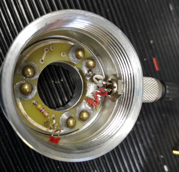
The circular body of the Wildhorse Probe is quite substantial. When the connector arrived and I was ready to proceed, I took a picture of the existing wiring and then snipped the cable clear. I enlarged the hole in the body wall to 9mm but then discovered that the mounting thread on the connector was not long enough protrude through the probe body wall far enough to pick up on the retaining nut. To overcome this I milled a flat area on the shell outer surface. The two connecting wires where then soldered in place on the fixed connector and then on the mating male connector on the free end of the cable.
Internal view of the probe after the Binder socket had been fitted
The next job was to make the new fixing rod. I always try to have 19mm silver steel available in my stock box. This matches the TTS collet outside diameter. I decided I would make a new mounting rod with the silver steel and I would increase the threaded mounting hole on the probe top to M8 from the 1/4″ size as supplied .
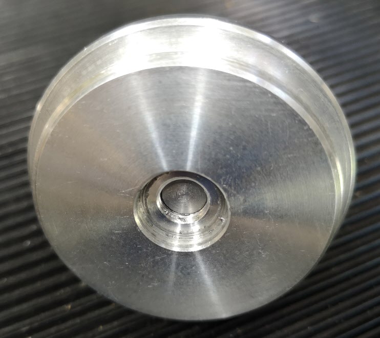
Top cover of the probe inside view of the M8 inside the spring retaining counterbore
The larger diameter would provide a larger shoulder on the rod to tighten against the probe top. Using M8 would allow the stud mounting hole to still sit within the pocket that retains the pressure spring. The rod was faced and turned to 8mm for 5mm or so and the M8 thread cut and undercut with a graver. The other end of the rod was faced and then a 45 degree chamfer turned on it. The finished rod screwed nicely into the top plate and the body now seemed to run solidly square to the central axis.
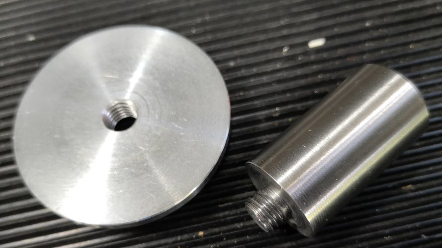
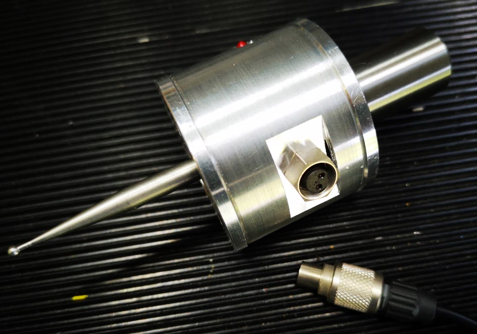
The new 19mm OD silver steel mounting rod and the outside surface of the top cover to which it is fitted.Finished modified probe showing connectors fitted with the flat milled surface and the new mounting rod.
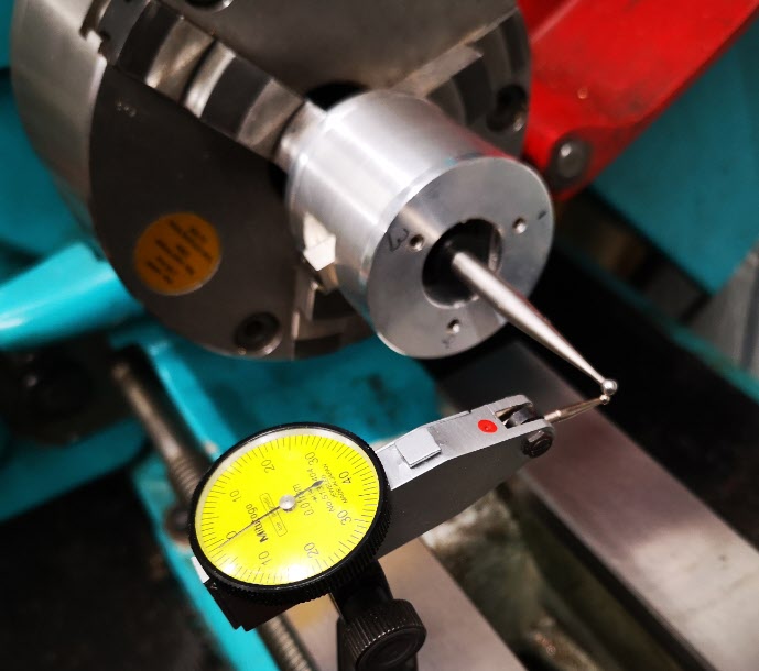
All operations were now complete and I mounted probe with its cable unplugged in the lather chuck with the new 19mm rod. I mounted my dial gauge on the lathe bed and set about centralising the probe ball. It was so much easier in the lathe with no cable to get in the way of things. Transferring the modified probe to the Tormach afterwards gave very similar centralising results.
Modified probe mounted in the lathe to allow easier access to the three centralising screws
So a typical workshop wormhole progression from job to job but as ever it was time well spent.
This write up is not for the purists with years of experience but is an explanation of how I thought through how to machine something over size that would not fit into my Tormach PCNC440 milling footprint as a single operation. Hopefully it might help others to grasp the process.
The challenge began when a local turret clock expert came to me and asked if I could machine a new Hour and Minute Hand for a clock he was working on. The Hour Hand was around 14” long and the Minute Hand some 18” long.
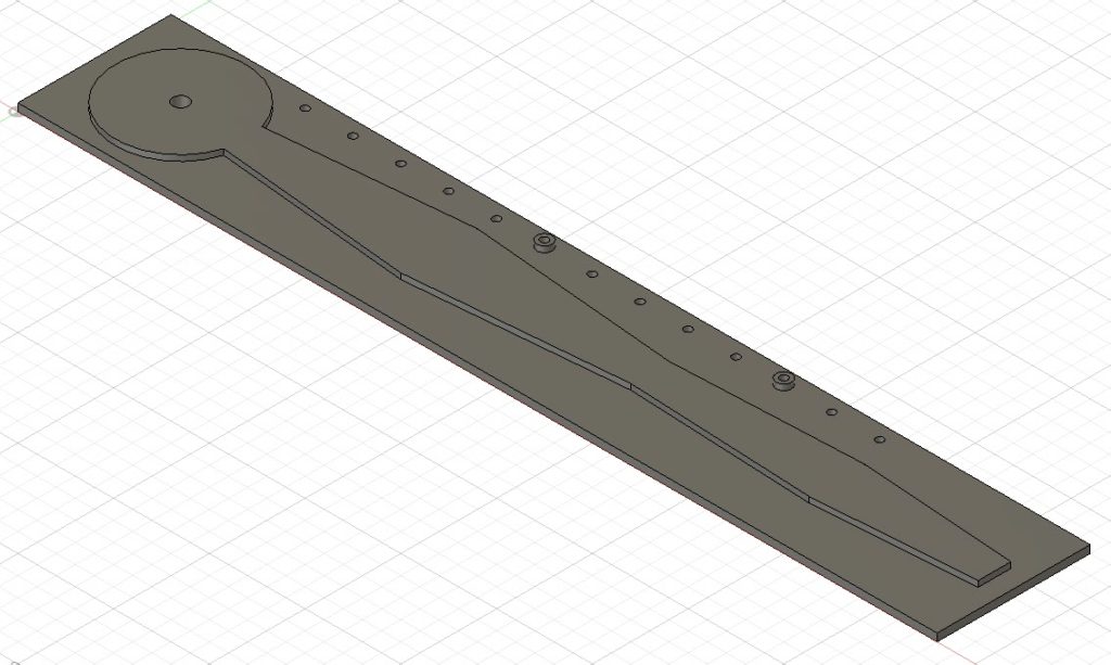
Here is the Fusion 360 view of the minute Hand.
Clearly these lengths were way outside the 440 table X movement (10”) so a plan was needed. There then followed a lot of staring into the distance at mealtimes and also at bedtime accompanied by vocal “hmmm”s as I tried to mentally visualise what was needed. This idiosyncrasy is something my wife has come to terms with over the years…..
My conclusion from this mental preparation was that I needed to be able to accurately step the stock across the tooling table and then take two or three bites at the profile machining.
What follows would almost certainly benefit from a video but sadly I am not set up for this.
Click the link below to download the PDF document.
Often a project comes along and it has you scratching your head how to go about it.
The following job was simple and it could have been hand filed but my preference was to machine it. The fact that I needed to make two added to my thinking. (aka – I am fundamentally a lazy person …. and I follow my father’s adage that if a machine can do it a human shouldn’t)
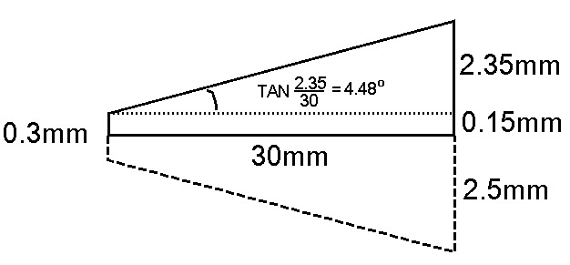
You can simply regard the challenge as looking like a screwdriver blade but I needed to have it with the flats exactly on opposite sides, the end of the flats needed to come together to a defined blade point thickness (0.3mm) and the length of the flat taper had to be a defined length (30mm). Here is a simple sketch.
What I am about to describe is not magic and I am probably teaching many a granny to suck eggs (is this a universal saying or quintessentially English and how did it originate ?) but it might help someone somewhere save a few minutes of their life.
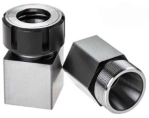
Stevenson Blocks in my opinion are the most elegant pieces of workshop tooling ever invented. They consist of an accurately machined block of steel with an ER collet mounting. Really quite simple. They come in different ER sizes and the block can be square or hexagonal cross section. These are they below and ArcEurotrade are one possible source.
If you have to machine a square head or hexagonal head on a piece of round stock they make the job so easy to run and make the result uniform, symmetrical and central. Likewise centre drilling of round stock becomes so much more simple. IMHO no workshop should be without Stevenson’s Blocks.
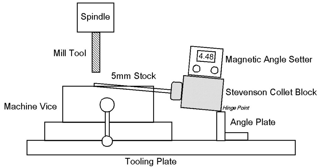
Back to the job in question. I drew out the geometry and calculated I needed to set the 5mm round stock at an angle of 4.48 degrees. Non scale sketch below. (Tangent rule – I can’t remember opposite and adjacent etc and remember it instead from – “Some People Have Curly Black Hair Through Persistent Brushing” where B = Base, H = Hypotenuse and P = Perpendicular).
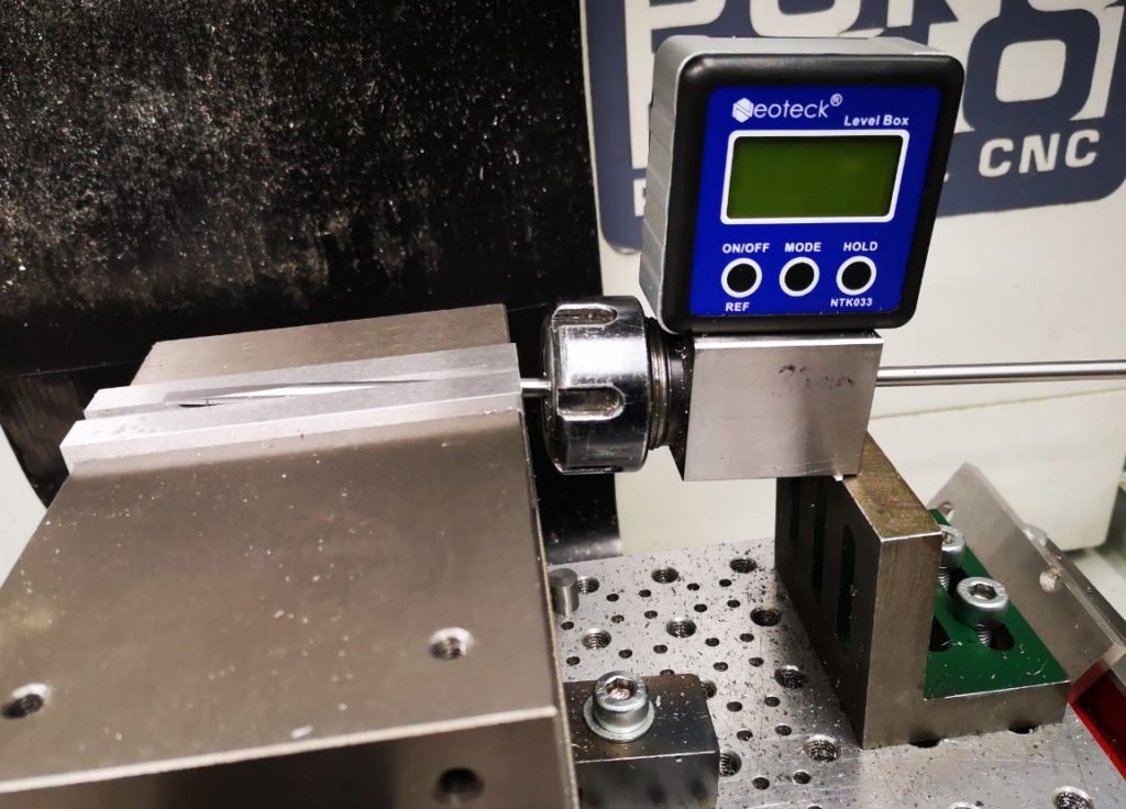
I could have simply set the stock in the milling vice at the required angle but it would be a real pain getting it correct and protruding the right amount to skim flat. The resulting set up was as follows and you can see how the Stevenson Block came to the rescue.
The 5mm stock was faced off and then marked at 30mm from the end and with a score line and then mounted in the Stevenson Block.
My angle setter just fits nicely on the Block surface and has a magnetic base. This setup makes it so easy set the stock angle by ‘hinging’ the Block up and down against the bottom edge of the Block and the angle plate surface. (Clearly for other angles the height of the hinging point support would need to change).
Once set, the cutter is traversed in ‘X’ up and down the stock until the run out point coincides with the 30mm mark. Once the first side is cut, the stock and Block (could this be the name of a pub for engineers ?) are rotated 180 degrees which is fix defined by the Block lower surface edge. The second side can now be run.
I said it wasn’t magic but it beats filing and is far more accurate than I would have achieved by hand. Good result.


 (Tangent rule – I can’t remember opposite and adjacent etc and remember it instead from – “Some People Have Curly Black Hair Through Persistent Brushing” where B = Base, H = Hypotenuse and P = Perpendicular).