I bought three Kafer dial gauges in an EBay job lot with a view to making a dual gauge holder as per Clough42’s design.
After some thought I realised that a single holder would suffice by just flipping the orientation of the dial gauge in the holder. Rather than machining the holder I opted to 3D print as this would be sufficiently robust when gripped in the QCTP of the Myford.
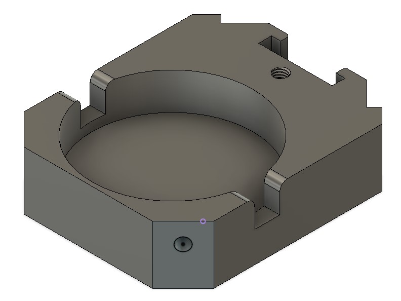
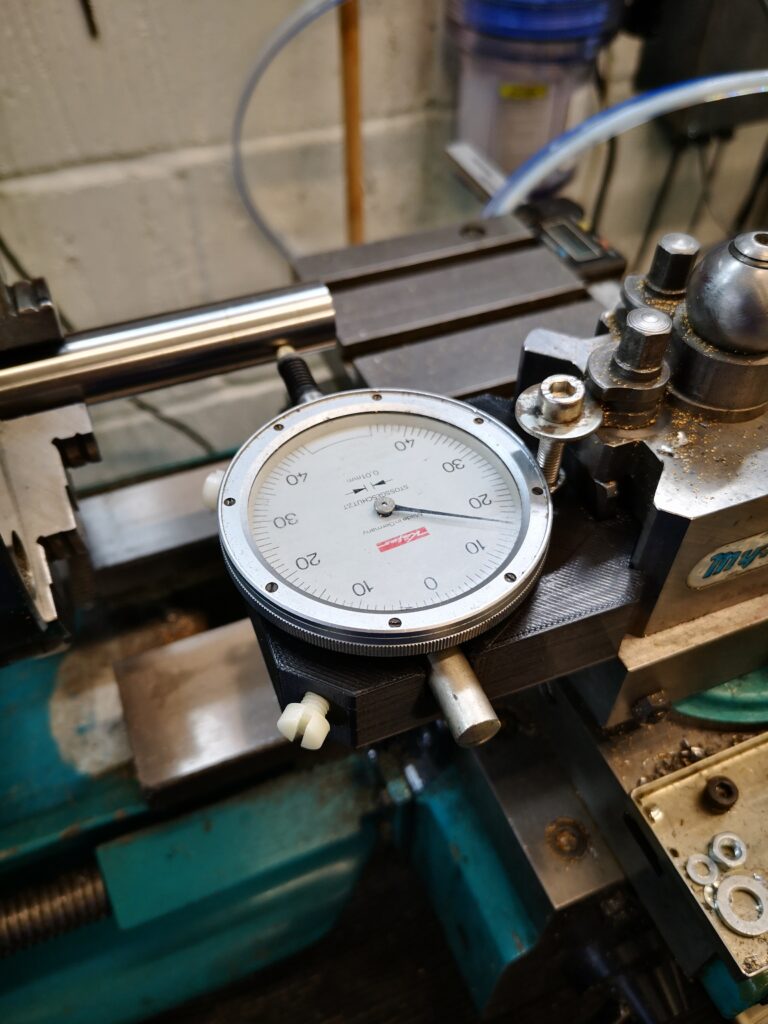
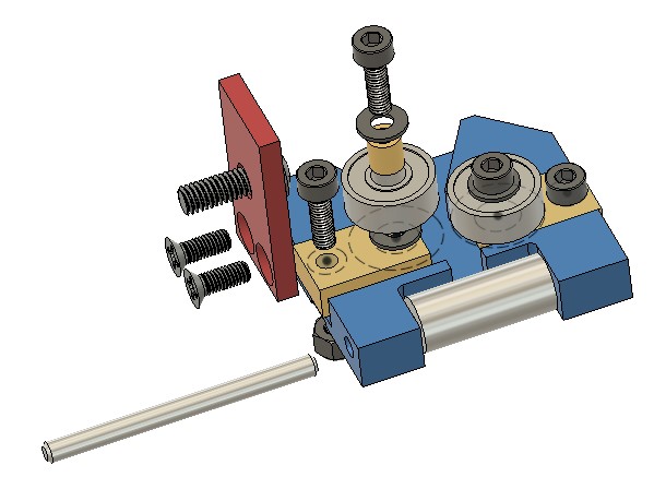
Here is the Fusion image and a picture of the finished holder in place. The gauge is gripped in place by two nylon screws. A M5 cap head screw acts as the height adjuster in the QCTP.
Fusion 360 model of the dial gauge holder to mount in the Myford QCTPThe dial gauge holder mounted in the Myford
The threaded holes are all M5 and 3D modelled in the print. They just need a run through with a tap to clean then up.
The following link has a ZIP file containing the Fusion file and STEP file along with the dimensioning sketch for the QCTP geometry.
I recently acquired a Femi NG120ABS bandsaw which you might think seems a bit strange given how much I talk on this site about my Burgess BK3 bandsaw. I regard them as two different animals.
The Femi has replaced my Kennedy for cutting stock ready for milling. The Femi auto feed facility means it can be left unattended while I get on with other things.
The BK3 upgraded with my modified guide assemblies is a more precise ‘cutting to a line’ device with the benefit of a wide throat for cutting sheet stock.
I am impressed by the Femi and by its performance. Speed of cut is excellent and build quality is very good. The vice action clamps well and is very rigid.
The one frustration with the Femi has been when loading material ready for cutting. You have to iteratively and repeatedly move the stock in the vice to match where you want the blade to be cut. This is easier with long pieces of stock but when you have a heavy short chuck of metal block with not much left between the jaws it becomes a juggling act. Likewise when cutting off line such as mitres. These situations mean constantly raising and lowering the cutting arm to check you have it in the right place.
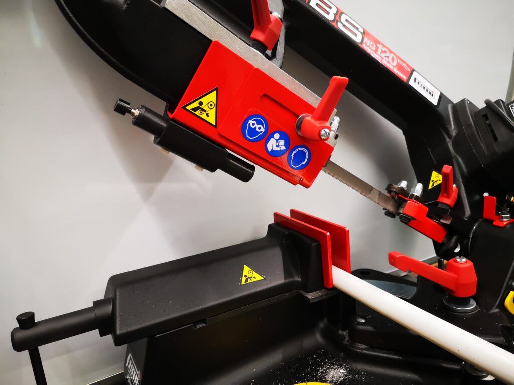
I have created a battery powered laser line module that mounts on the Femi blade guide and which will show where the blade will cut. It clearly isn’t for everyone’s taste but it makes life just a bit more simple ! As Jimmy Diresta says … ‘I’d rather have it and not need it than need it and not have it’.
Image showing the laser alignment guide mounted on the Femi NG120ABS bandsaw
Here is a pdf file containing the write up giving details.
Because of the interest shown, if there is sufficient demand I could arrange for some PCBs to be manufactured offshore. Let me know via the email in the footer.
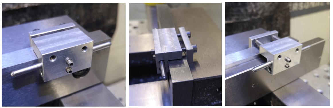
There are a number of lower cost CNC milling vices (vises) available on the market that do not have jaw geometry with grooves for tooling fixtures and vice stops. Admittedly their jaws could be machined to add this facility but many of these vices have hardened jaws which presents more of a problem.
My CNC vice came from the UK supplier ARCeurotrade and is from their ARC Versatile SG Iron Milling Vices range. I have the 100mm wide jaw version and the jaws are just over 11mm (7/16″) thick.
I have a simple plate that acts as a stop that is flush with the end of the jaws. This makes use of existing holes in the vice body but often I need to have a stop internal to the jaw footprint. Juggling then results with all manner of Heath Robinson solutions.
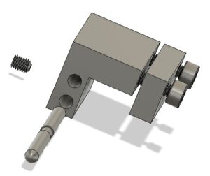
My design is simple and clamps onto the thickness of the jaws.
There are two M3 clamping screws and there is enough adjustment on these to allow a parallel to also be gripped should it be needed.
CNC vice stop showing clamping onto the vice jaw and also when used with a parallel
I allowed for two positions for the stop rod and the rod is held with a grub screw in each. There is a central burr clearance neck on the rod so the grub screw does not damage the surface of the rod and make removal difficult. Clearly the rod could be simplified to have just a single fixed position.
The rod can have rounded ends or it can have ball bearings glued into a cavity on each end of the rod. The ball bearings would give a higher resilience to damage.
So nothing really complicated or rocket science with just an hour or so of workshop pleasure. The size can be adjusted to suit your vice jaws and the material can be whatever is in the junk box.
Here is a link to the 2D drawings that were created in Fusion 360.
Burgess BK3 Final Modification – Lower Blade Guide
This is the final piece in my Burgess BK3 bandsaw upgrade jigsaw. Having successfully replaced the top guide with a double bearing assembly my attention turned to the lower guide. Using the same principle as the upper guide I came up with the following assembly.
Stylised Fusion 360 image of the replacement lower guide assembly on my Burgess BK3 bandsaw
This seems to work well and is straightforward to implement. The bearings are standard 1/2″ size parts from Bearing Boys. These need a small brass bush to mount them on the sliding brass blocks. The blocks need a single M3 washer to space the bearing from the block and the body.
The blade pressure roller is made from silver steel and can be heat treated to improve wear from the blade edge.
The mounting bracket arm picks up on the original M5 mounting screw concept. The bracket could be milled onto the main body as a CNC operation but the two part assembly works fine and is very rigid in operation.
The link below is a complete set of notes and drawings pulled into one ZIP file to cover all the modifications I have done and separately document in my blog and other author’s notes that I have come across. I hope that helps.
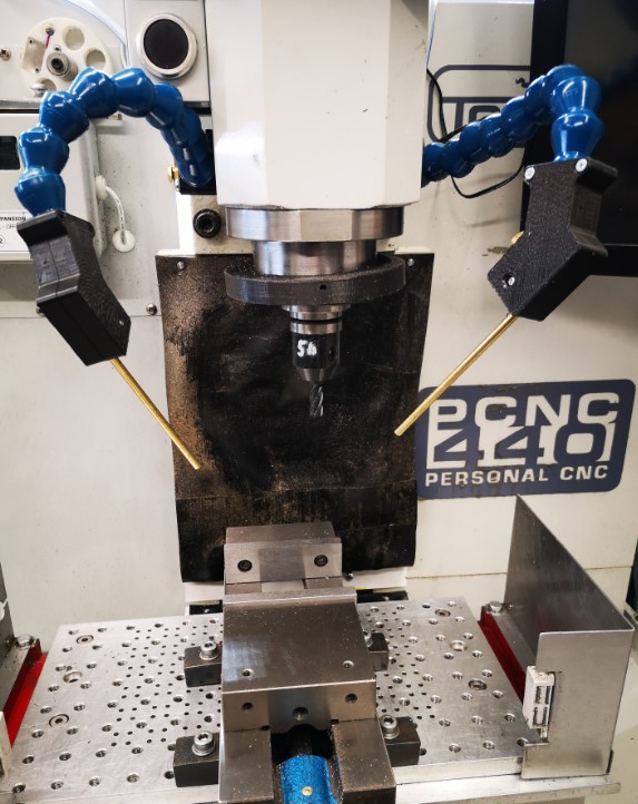
Apart from working on the Thwaites clock parts, I have also done an upgrade to the mounting of my Fogbuster coolant nozzle installation on my Tormach 440. This was triggered after viewing and being impressed by Clough42’s idea. The Fogbuster is a great way to clear swarf and apply coolant. The Fogbuster is normally supplied with a magnetic mounting arm but James’ modification uses LocLine gooseneck components to provide a much more flexible ‘aiming’ capability.
Something to be aware of – James recommends a download from GrabCAD for the 3D files of the two halves of the nozzle holder. These had been uploaded by contributor Br BRB. These were apparently publicly available via GrabCAD. James slightly modified these and was offering them as a free download from his Thingiverse folder. He has since had to remove them for download due to commercial issues. BrBRB has also removed the original files from GrabCAD and is seeking to sell these as finished items. I was lucky to have downloaded the files before the politics cropped up. I still have the downloads.
James also advocates fitting a second identical nozzle to the Fogbuster to avoid coolant and air shadowing. I contacted Fogbuster in California and a very helpful lady called Rachel organised an upgrade kit to provide a second feed from my existing coolant reservoir.
Dual Fogbuster coolant nozzles on Tormach PCNC440 using Clough 42 flexible nozzle idea
It turned out Rachel was from Bristol UK so it is a small world and we had a good chat. I have fitted both nozzles to the Tormach. With a pressure of around 10 to 15 psi, the reservoir feeds both nozzles very well and is a huge improvement in use.
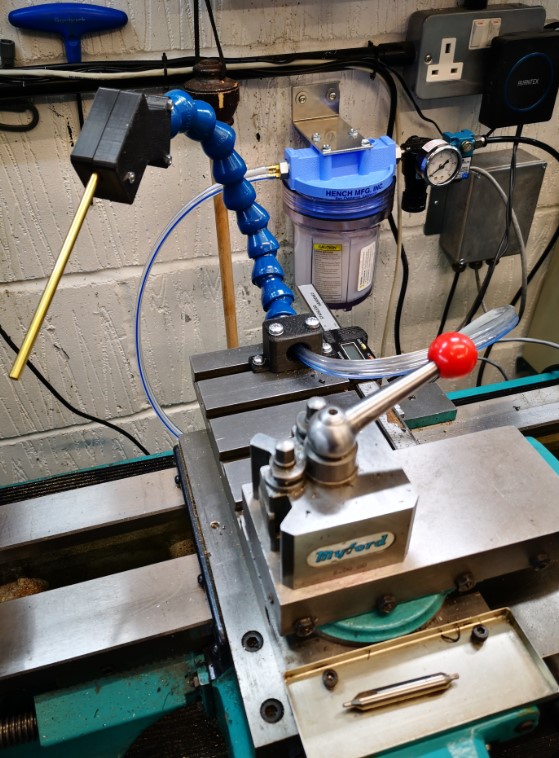
As I was facing a shipping charge from the US I figured I might as well top up the package so I have also splashed out on a baby version of the Fogbuster to fit to my Myford lathe. This uses the same idea but with slightly different mounting that fits into the T Slot on the Myford saddle. I already had the 3D model of the T Slot strip from the ‘bits tray’ installation.
Baby Fogbuster mounted on my Myford Super 7 saddle based on the Clough 42 flexi nozzle idea
Another pair of incremental asset improvements successfully installed. I suppose I had better get on and make something now.
Back to ‘the clock’ …
UPDATE 2 : – The 3D printed ball joint kept working lose on both the milling machine fogbuster mouunts. The more I tightened the screws to grip it tighter, the more the 3D components began to crack and give way. The solution was to fit brass inserts into the 3D prints. Problem solved. Incidentally there is a good review of such inserts on CNC Kitchen.