My side interest in bees brought this booklet to my attention where the author Jonathan Powell describes how he created a beehive from a couple of scrap wooden pallets.
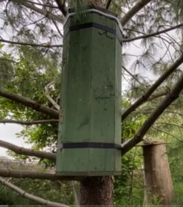
The hive is intended just for the bees with no intention of humans taking honey. It provides them with a tree like cavity to inhabit in keeping with a natural hole in a tree. We humans seem to chop down our trees at an alarming rate and the potential for ancient trees with cavities suitable for wild bees diminishes by the day.
The hive has an inner core and an outer core with an insulation layer between the two using the sawdust created in cutting the pallet material. My engineering brain kicked in and below is a spreadsheet that helps calculate the dimensions required for a multi-sided structure having the required 40 litres volume that bees appear to prefer.
Plenty of time is available to make one of these before the spring swarming period starts.
I do not claim to be an expert on bees but my interpretation is that such hives with high levels of insulation lead to less stress in the occupants. This in turn means they are less prone to disease. There is also much published information about the stress induced by having high density clusters of ‘domesticated’ bees leading again to disease. Having simple well insulated hives for the wild bees to populate in relative isolation to each other must help these problems albeit at the expense of man being less able to raid honey.
Here is an interesting link on the interaction of wild bees and domesticated bees.
For those wanting an interesting read I recommend ‘The Honeybee Democracy’ by Thomas Seeley. Fascinating book.
Similar or related subjects : –