Qidi X Smart 3 MCU comms failure

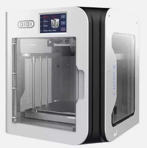
My two Qidi X Smart 3s have been a good investment but like all things, they are only as good as their ongoing performance.

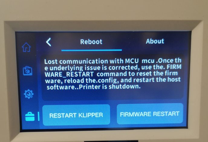
I recently had a few instances whereby my UK based printer stopped mid print having lost comms. This was the error message.

This error increased in frequency to the point where this message was present from switch on. In the process of this I learned that a good pointer to this problem is zero temperature readings on the opening LCD status screen.

Now at this point I must emphasise that in my experience Qidi support is excellent.

I opened a support dialogue with Qidi and between us we began to analyse the issue. The general initial consensus was that it was likely to be the USB-C umbilical cable connecting the motherboard to the print head. Other things that they suggested I test were whether I had too many files stored on the machine (weird one) or a hot end fan or the nozzle heater having gone short circuit both of the latter would lead to a high current demand via the USB-C. These were easy to test and checked out OK.

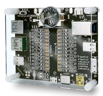
Focus therefore moved to the USB-C cable. This carries the power suppy to the hot end together with the control and measurement data stream between the motherboard and the hot end adapter board. The cable tested faulty (see the tester details below). To elimate whether this was the only fault I externally connected a uGreen equivalent USB-C cable but the MCU fault was still present.

The conclusion Qidi and I collectively arrived at was that there was an additional fault either with the motherboard or the adapter board.

Qidi sent me replacements items on a fast delivery from China at no cost to me. This is an example of the level of support you get from Qidi.

On receipt of the shipment it was a matter of substituting each item in turn to identify the culprit. This revealed that I had not just a faulty USB-C cable but also a faulty motherboard. The USB-C cable has to withstand a lot of flexing as the print head zooms around the chamber so I think this might have led to a fatigue related failure of the cable. I wonder also if the cable fault caused some form of knock on transient spike that damaged the motherboard.

While diving in and changing these components might seem a bit daunting, there is really no difficulty swapping them out. Remember to take a picture of everything before you commence. By far the most tricky aspect was physically removing and replacing the USB-C cable as it weaves its way round the build chamber via various slots in the cabinet.

One thing to note is that replacement motherboards, once fitted and working, may need to have their firmware updated to present issue. This is a matter of downloading the new file from the Qidi website. You have to unzip the file (a *.rar compressed file which is WinZip compatible) and then copy the file to a USB stick which you in turn plug into the printer USB port before following the onscreen instructions. Note it is important how you load the file on the memory stick in order for the auto update routine to initiate.

One outcome from all this activity is that I would recommend a USB cable tester. I bought one in from Amazon which is very analytic and immediately showed me I had a dead cable. For GBP16 this will certainly remove any future frustration caused by damaged cables.

Overall not an ideal distraction from more important projects but as ever with this type of problem, you learn more about your workshop tooling and your associated knowledge base expands.

Thank you Qidi for all your help.

Links to similar or related post are listed below : –

3D Printed Jigs to the rescue

I have been struggling with seeing where I am going on my Polly V live steam locomotive on the Club raised level track. It is the time of year where the cold weather quickly condenses the exhaust stream and you end up heading into a ‘white out’. This is not too bad if you trust the track but if there are ‘hokey cokey’ sections where your weight distribution is critical to remaining on the track it can be a bit unnerving and not good for your underwear.

I resolved to solve this before the New Year’s Day running session by making an exhaust diverter. I sketched this up in Fusion to use 32mm (1.25″) brass pipe forming a simple 120 degree Y shape. (The chimney bore down to the petticoat is 32mm).

The design was easy to model in Fusion but did require me to revisit the ‘plane on a path’ function. I first printed a 3D model of the diverter and this fitted nicely down the funnel. The next problem was going to be cutting the 30 degree angles on the end of the brass tubes. What was needed was some means of holding the tubes in the bandsaw so they could be flipped 180 degrees while making the 30 degree cuts and while also maintaining the protruding length. It struck me that I just needed a 32mm bore Stephenson Collet block with a reference edge – something not currently to hand nor in regular demand in my workshop. Then galloping over the horizon came my Qidi X Smart 3 demanding to provide one.

Back to Fusion and a few quick sketches gave me a model to hold the tube with a grub screw grip and with a reference placement lip on the front edge of the block. This worked a treat and I quickly had the three pieces of brass tube cut to length and mitred ready for assembly.

The preparation ended up being the easy part as I now had to hold all three pieces carefully in position while I braized them together. I reverted to three pieces of wooden rod gripped in each tube and the rod in turn fastened down onto my brazing hearth bricks. Crude but effective albeit potentially a fire risk.

The moral to the story is that in the past I would never have considered machining up a relatively large block of metal just to cut six mitres on some brass tubing. 3D printing has completely changed my approach to model engineering and the PLA recycle bin is now busier than the metal recycle bin (that used to contain not just swarf but also those ‘didn’t quite get it right’ rejected parts). It is not only this change but also the ability to get on with something else while the 3D printer creates your solution or path to a solution or just your ‘I wonder if that would work’ dreaming.

Result – I can now see where I am going as I chug round the raised level track and my laundry bill is much reduced. Here are some final images.

Just a closing thought while in Fusion mode – how about a more flexible version ?

Links to similar or related post are listed below : –

3D Printed Length Gauge for In Barrel Mainsprings

I had received a clock to repair and wasn’t sure if the mainspring was correctly dimensioned. I remembered that William Smith had described a gauge for checking this in his book ‘Clockmaking & Modelmaking Tools and Techniques’ (pages 21 – 26). This gauging tool consists of two profiled plates that slide together to overlay the end view into the clock barrel. Bill’s design used 1/16″ brass plate but it struck me that a 3D printed version would be equally suitable and much quicker and easier to make.

In use the gauge is overlaid on the end view of the barrel as shown below. The point A is aligned with the outer diameter of the barrel arbor. The top plate is then slide until the inside edge of the barrel wall is aligned with point B. For a correctly chosen mainspring it should align with the corners C and D.

I sketched Bill’s design in Fusion 360 and extruded the two component parts to have a 2mm thickness before printing on my Qidi X Smart 3 in PLA. The two parts are fastened together to be a sliding fit with two M4 screws. The threads for these are modelled in the 3D print. A handling knob can be added in a similar fashion.

Here is my PLA printed equivalent.

The STL print files can be downloaded on the link below. It is not something that you will use every day but just a ‘useful to have when needed’ item. “Better to have it and not need it, than need it and not have it” (Jimmy Diresta).

Links to similar or related post are listed below : –

Superb Qidi Technical Support

One of my X Smart 3 printers suddenly started to show an error message that the temperature sensor on the hot end was not rising correctly.

I emailed Qidi support and talked with Annie. She said it was a hot end failure and would get a replacement hot end assembly shipped to me. This was on Monday. The replacement hot end arrived last night (Wednesday) and I fitted it this morning. Printer fixed and back up and running. I was staggered by the service.

Qidi might not be as well recognised as Bambu Labs but Qidi’s Technical Support certainly know how to look after their customers. Lovely machines and superb back up.

Links to similar or related post are listed below : –

Creating Customised Threads in Fusion 360

As ever this started off with a need and from the need came some learning.  In my experience such needs are always welcome for the resulting learning benefit but inevitably lead to a few hours of frustration.

We have a small Jacuzzi spa at our home in France.   It has two cartridge filters that are screw mounted into the sump of the spa.   The threads on the cartridges are plastic and are loosely defined as 2” SAE spec. (I think SAE is a fine pitch thread (?) and as the filter threads are around 5mm thread to thread pitch, they don’t seem to me to be fine pitch).

When filling the spa from empty, Jacuzzi recommended that the filters are removed and the filler hosepipe nozzle is wedged into the outer vacated of the two filter holes. The nozzle has to be jammed in place by packing a cloth or sponge around it.   Filling via the filter mounting ensures the spa fills from the bottom up with minimal potential for an airlock in the pipework.

The problem with this is that the filler hose tends to have a mind of its own and when your back is turned it will liberate itself from the filter hole and whiplash round like a demented cobra and give you an unexpected bath.

After one such soaking I resolved to stop this happening.   What was needed was an adapter plug to fit into the “2” SAE” socket that would accept a standard hose push fit connector.  This would hopefully keep the rampant serpent retained during the filling process.

I opted to use a standard commercial male hose connector for the interface to the filler hosepipe. These have a DIN Pipe thread specification (G26.441 x 1.814 mm).   This left me with the need to model the 2” SAE from scratch which on inspection appeared to take the form of a pseudo Acme profile but with an asymmetric thread to valley ratio.

Having failed to find anything helpful on the Internet I set about creating a custom thread in Fusion 360. New experience ….

Here is the resulting adapter. 

The attached ZIP file below has the full write up, the STL file and the source Fusion file.

Links to similar or related post are listed below : –

Verified by ExactMetrics