I am still building up to automated wheel cutting on the Tormach.
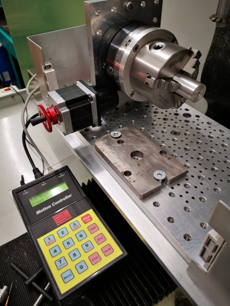
I have mounted the Sherline CNC rotary table on my tooling plate and the table now needs a chuck or collet mounting plate fitting. This will grip the super glue arbors that I use for holding the wheel blanks while cutting.
I decided a chuck would be the best option and bought in a low cost 80mm three jaw chuck made by Sanou. These are available from a number of outlets on EBay. It is supplied with internal and external jaws and a chuck key.
It arrived very quickly and felt horrible. Turning the chuck key was really gritty and jumpy. Rather than sending it back I decided it would be worthwhile stripping it down to see what was going on.
I have never attempted stripping down a chuck before and to my surprise it was relatively simple. I first removed the three jaws, then the three rear cover retaining screws, the three adjuster retaining pins and finally the three adjusters. In theory then the spiral plate should drop out. But it didn’t and it took some serious tapping with a soft tool to remove it.
Having got all the bits apart and in front of me I began to deburr all the sharp edges that I could find. What seemed particularly important was to clean up the spiral plate internal diameter as this seemed to be the tightest fit. A flat diamond coated file together with a triangular one were the best tools to use. Once all this was done I put all the parts in the ultrasonic cleaner with hot water and detergent. There was a surprising amount of grit in the bottom of the tank once cleaning was finished.
Re-assembly was the reverse with everything being coated with moly grease before assembly. It was now a completely different chuck. Beautifully smooth.
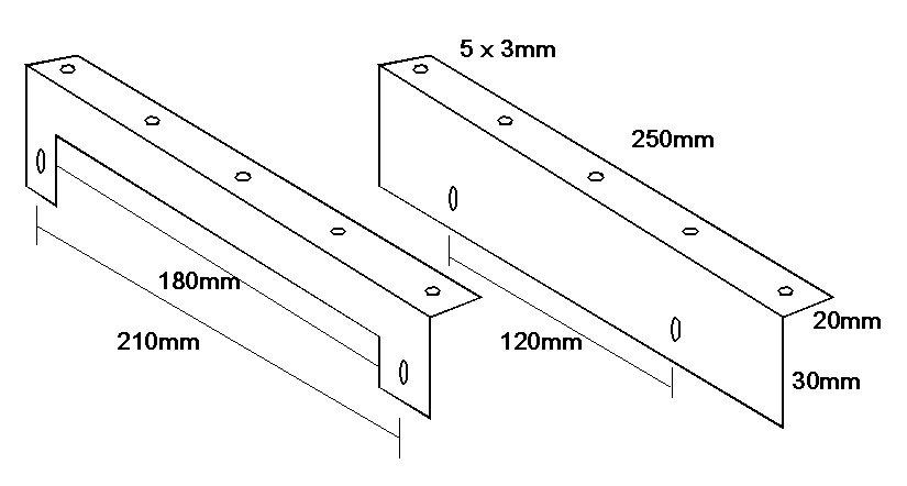
The next problem was mounting the chuck on the CNC table. I first made a mounting plate with three M6 clearance and counterbored holes on the PCD mounting holes for the chuck (66mm) and four M5 clearance and counterbored mounting holes to match the cross slots on the CNC table (96mm). I also put a 16mm clearance hole in the centre of the disc to match the chuck bore. 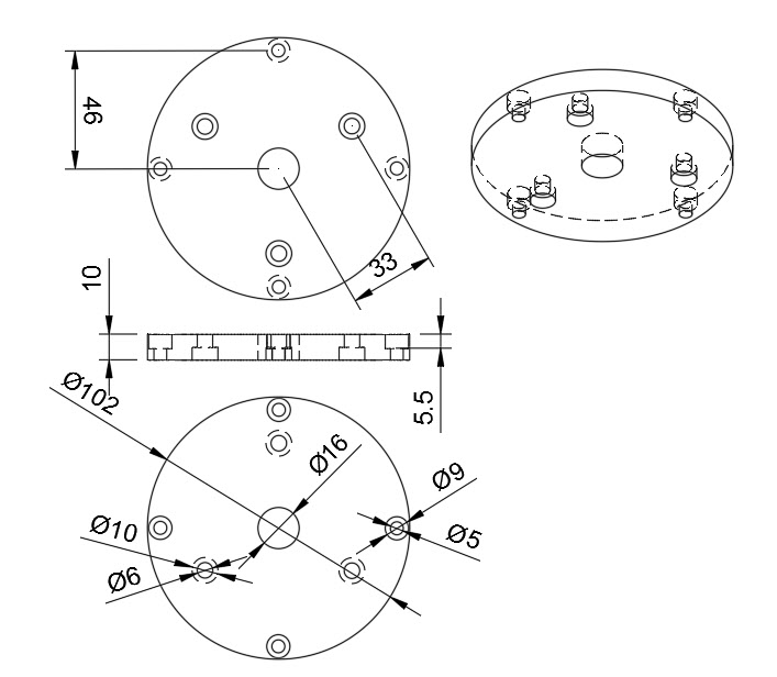 Next problem was how to centre the chuck on the rotary table. Fortunately the rotary table has a central, tight fit 11mm (0.25″) shouldered hole leading to a UNC 3/8″-16 screw thread. This is the mounting for use on Sherline products. I cut the UNC thread on the end of a piece of 11mm silver steel and screwed this in place at the centre of the table. This was perpendicular to the table face.
I then fitted the chuck to the backing plate and lowered the chuck and plate assembly over the 11mm rod and loosely tightened the jaws. This allowed the chuck to just rotate so that the four table slots could be aligned with the four holes in the mounting plate. These four screws were also loosely tightened against the T slot nuts and then the chuck pushed firmly down and the jaws closed tightly. The four table mounting screws were then tightened. The chuck should now be centrally placed and tightly in position.
The 11mm silver steel centralising rod could be unscrewed and removed. I put a piece of 20mm silver steel in the chuck jaws and checked the run out as being +/-0.05mm which to me didn’t seem bad and more than adequate for the task intended.
A new experience and a good end result.
Still got the GCode to sort out to automate the process … and finish off the USB expansion unit to increment the motion controller.
Update : –
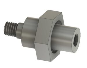
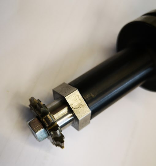
I found that just a straight 11mm rod with a 3/8″- 16 UNC thread on the end was not reliable in sitting square to the CNC table surface. This resulted in the chuck running eccentrically. I modified the centring rod to have a collar fitted (16mm diameter to clear the chuck central hole) which was silver soldered in place and then trued up on the lathe. This modification allows the chuck to be fitted and centred easily and quickly each time. Here is the Fusion 360 model.
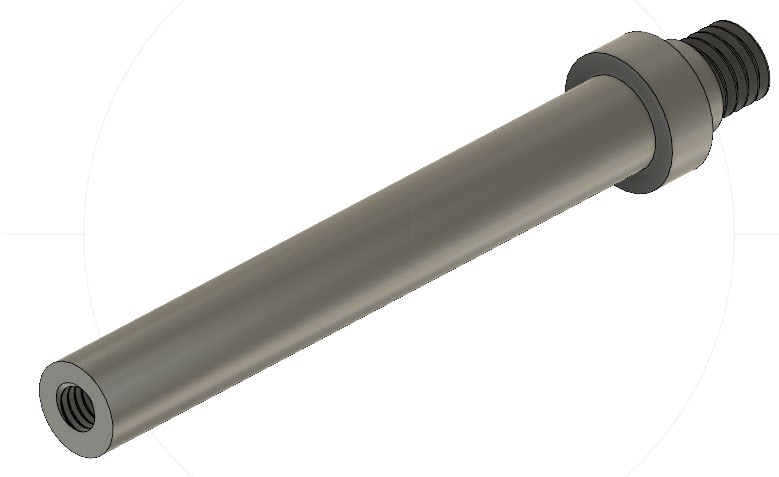
I also added a M6 threaded hole in the end of the rod to allow the fitting of a cap head screw. This is Loctited in place and is used to release the rod from the rotary table central threaded hole once the chuck is in place. An alternative would be to mill a hex head on the end of the rod but I took the lazy way out.
Similar or related subjects : –
- Fanttik super tool is well worth a look
- Small handheld vacuum cleaner
- Eccentric Engineering Turnado freehand turning tool
- Rotring 300 2mm clutch pencil modification
- Kindling Cracker – a safer option
- SINO SDS2MS DRO repair
- A useful Amazon sourced small item storage system
- 3D Printed Threads Modelled in Fusion 360
- Three axis stepper controller PCB in stock
- Myford Super 7 Large Bore depth stop
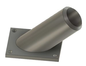
 It is made from a piece of 19mm AF hexagonal steel bar with the hexagonal flats going to be used as a tightening it in place in the Tormach arbor. My Myford Super 7 when used with a 3 jaw self centering chuck is not bad on concentricity but for really accurate centering I swap the chuck for a collet face plate instead. This job was going to need both.
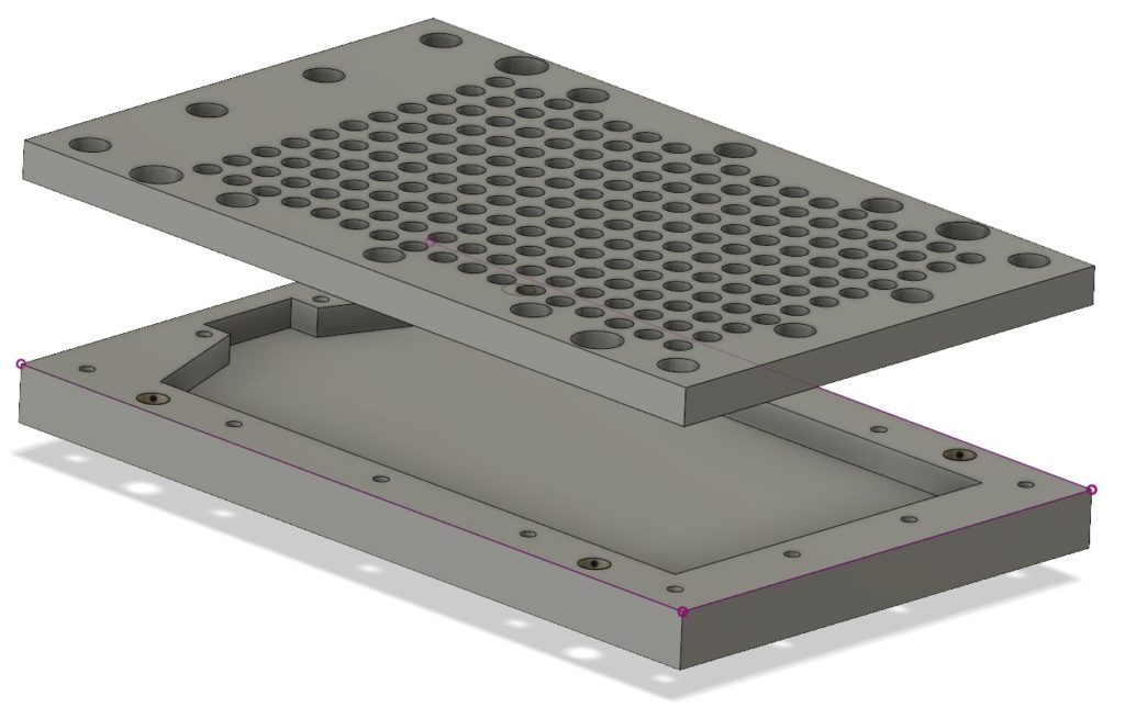
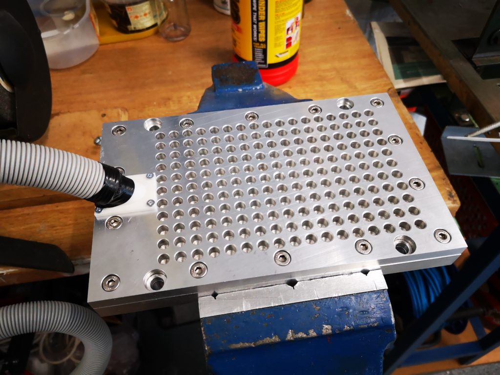
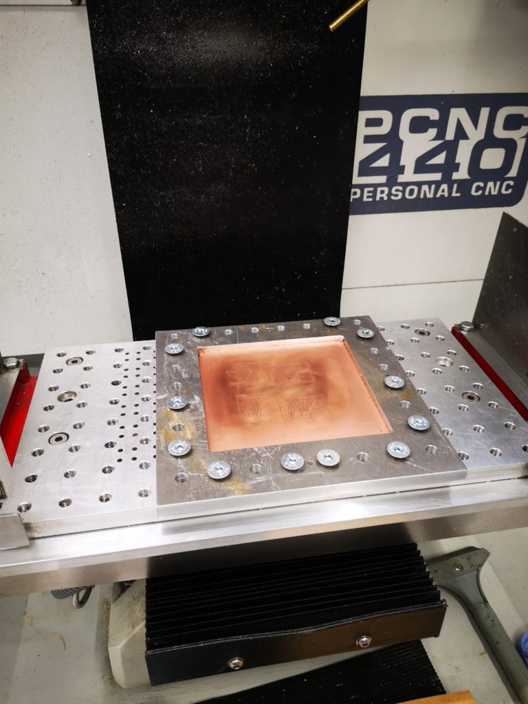
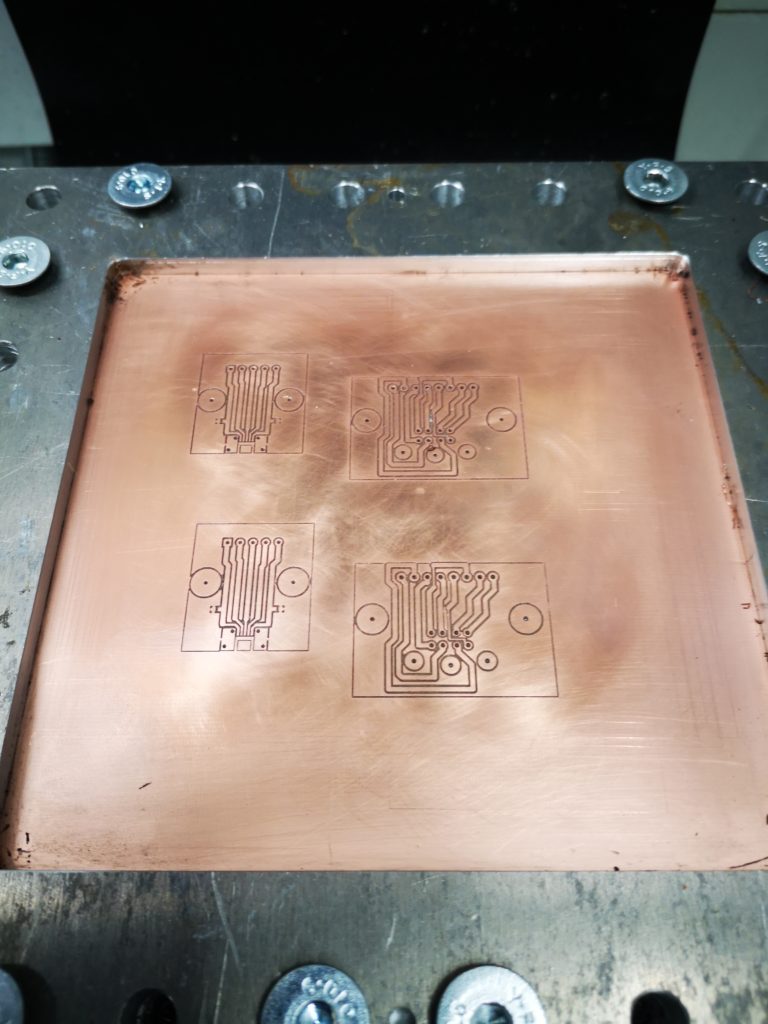
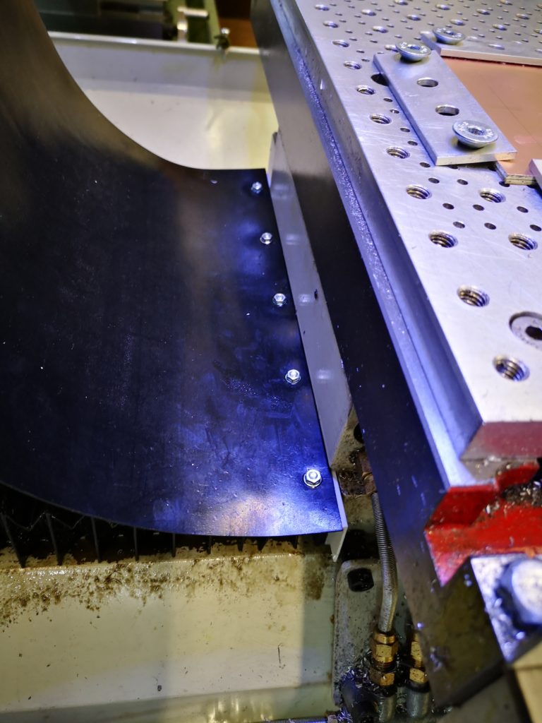
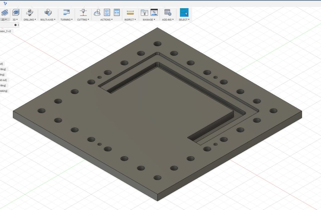 The outer holes are for the M8 clamping to the table and the four smaller holes are the tooling holes. Being tight with my materials I did not want to just mill out the centre of the plate and have a mountain of swarf (chips). Instead I designed it with two slots as shown, one for the clamping surface and one that almost cut through the stock. The partial cut was to ensure the central piece did not flip out once cut free and damage my cutter. First one half was drilled and cut and then the plate was rotated 180 degrees and the second half cut. This left the central island just held in place by less than 0.5mm of material. This was easy to hand cut through to liberate the central area. The plate was then turned over and the cut edge cleaned using the same tooling position and doing the same 180 degree rotation. To my surprise the rotation process on the tooling pins worked very well with only a minor step transition at the overlap point on all cuts. This was probably more down to my 3.7mm tooling pins being not quite concentrically turned from 4mm silver steel. With this finished I now had a much more robust clamp for the PCB material. I had made the clamping step 4mm deep so I could put sacrificial backing boards behind the PCB being run. This would allow drilling through as needed. Checking the flatness of a clamped PCB blank with my Haimer showed variation of a few thou in the top surface of the PCB Z position. The worst case variation in Z was at dead centre where the PCB’s natural bow was most dominant.