The desktop computer in France was running on Win7 and Fusion 360 needs Win10 or above. I brought the machine back with us to the UK and decided to upgrade it to Win10. I’m not yet prepared to step up to Win11.
As part of the upgrade I took out all the existing drives and fitted a 500GB SSD. I loaded Win10 which went to plan and used the same email address and PIN entries for the user ID as I use on my UK machines.
Win10 came up with the usual generic blue opening screen and I then sat and began to plan what programs I needed to load for use in France. After about 15 minutes the blue Microsoft desktop screen disappeared and was replaced with the same desktop image that I use on my UK screens.
So tell me how does the new SSD and Microsoft know that this is my go to image for a desktop ? It can only be registered in the Microsoft cloud storage against my account details. Which is slightly worrying.
I had a recent request to machine some panels in 3mm thick ACM. This has a polyethylene core sandwiched and bonded between two thin sheets of aluminium. The sizes of the various panels requested could not be easily accommodated on my Tormach PCNC440 CNC mill so I had to dust off my CNCEST 3040T baby router. Five out of the six panels would fit inside the 3040 working footprint but the sixth required me to revert to a two setup movement of the workpiece in the Y axis. My write up of this stepping process for oversize objects can be read here.
The CNCEST 3040 has a maximum spindle speed of 10k RPM and is controlled using Mach3 with all the frustrations that brings to the party plus manual tool changes etc etc.
I received DXF drawings of the panels and these were imported into Fusion where they were simply extruded to 3mm before processing in Fusion Manufacturing. Each CAM operation was exported as a separate function into Mach3 regardless of tool changes. This gave me step by step control.
I used a 12mm thick MDF sacrificial (spoil) backing board to mount the panels. As all the panels were of the same general dimensions this made mounting the panels a repeatable process using a fixed matrix of woodscrews into the MDF. The 12mm depth of the mounting board made the tooling pin reference holes for the Y move much more rigidly fixed and as a result more repeatable to use.
The main problem encountered was that the ACM does not readily adapt to machining with conventional end mill cutters. I tried using my stock 2 flute parts and these would skim on the top aluminium surface while the plastic underneath deformed to the Z axis increasing pressure. Once sufficient pressure was exerted the tool would finally bite into the aluminium and punch through into the plastic with a noticeable ‘clunk’. This played all sorts of havoc with the Z axis height referencing and also lead at one stage to the Z axis stepper coupling working lose.
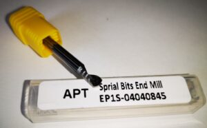
The solution was to go to a single flute spiral cutter style. These were purchased from APT Tools (UK supplier). Hot knife through butter comes to mind with the result of this change.
The single flute spiral end mill from APT Tooling UK
For straightforward hole cutting I used standard PCB carbide drill bits from Drill Services (UK supplier). These are nice to use as all have a standard 1/8″ shank which makes tool changing a little bit easier.
Once all these frustrations were overcome the process became much more repeatable albeit with one or two curved balls due to Mach3 lock ups. Have you ever enjoyed trying to manually re-reference a half finished job ? …..
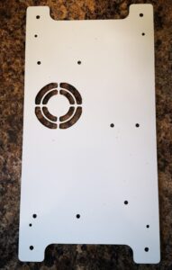
The finished largest panel that required a two step movement in Y axis
More accumulated knowledge gained and lots of black plastic swarf (chips) to clean up before it could migrate everywhere into the house.
Today while in the workshop running a CNC metalwork job and then following this with running a quick PCB artwork, the following came to mind.
These days since I bought the ITTP Hallmark probe I rarely use my Haimer Taster to do my referencing. It still has its uses but less and less so. A good example is when remounting the CNC vice on the tooling table. I use the Haimer to give me a running check on the vice jaw axis tracking. Beyond that the ITTP in conjunction with PathPilot probing routines meet all my referencing needs to a level of accuracy that suits.
The other thing that stuck me is how automated my process for milling printed circuit board prototypes has become. Fusion 360 Electrical module becomes more familiar to me with each passing project. It exports my PCB designs as Gerber files to import into FlatCAM. After a few clicks in FlatCAM I have a GCode file for drilling and routing. The PCB blank is gripped on my small vacuum table ready for milling and the ITTP probe references the spindle. My recent use of kitchen anti-slip material as the sacrificial layer between PCB and vacuum table top surface has made the grip on the vacuum table so much easier to achieve. The overall PCB process, whether single or double sided, has become quick, easy and repeatable. Once the board is milled I can get a reasonable looking tinned finish using a hand soldering iron and copious amounts of flux.
Techniques almost subconsciously evolve and sometimes you need to step back and see how far you have come along the road. The alternative view might be that this ‘lazy man’ has just become even more lazy.
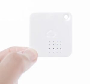
I have installed a network of low cost wireless sensor tags to monitor our homes here in the UK and also in France. These are really useful little devices that measure temperature, humidity and motion such as a door opening.
They store their readings and can be interrogated via the Internet to see a profile history. They also have limit alarm trip options that push messages to email to let you know if anything untoward is happening. The product website is here.
Image of a tag device
As examples of their use, here in the UK we have one fitted inside our freezer to check that the temperature is within limits. Should the freezer fail or the door be left slightly ajar we get a message.
In France we have one installed inside the spa pump cabinet to check the temperature over winter to check that the pipework does not see freezing temperatures. This works in conjunction with a greenhouse tubular heater that is also in the spa cabinet wired to a frost stat set to 5C degrees. If the temperature drops the pipes are protected by the heater coming on. If the AC mains fail the heater will not come on and the sensor tag warns us to ask the neighbours to visit and check the electric distribution panel as we do experience frequent power outages.
Under normal circumstances the tag internal CR2032 battery will give a reasonable battery life approaching 12 months. These are not normal circumstances however and due to COVID we have been unable to visit for over 12 months. As a result all the tags at our house in France have dead batteries. Their use inside freezers and outside in the cold degrades the battery life achieved. This got me thinking about fitting a larger battery pack to the tags in France to help longer battery life monitoring while we are absent.
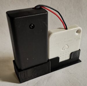
My solution is not elegant but functional. I have wired an external battery pack containing two AA batteries to the tags. The battery box is a commercial item and is available in packs of five on EBay. They come fitted with an ON/OFF switch and more than enough cable to connect to the battery contacts inside the tag.
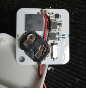
The tag case can be sprung open with a fine screwdriver or wood chisel and the PCB removed. The dead battery can be slid out of the PCB battery holder. There are a string of five module probing lands at the foot of the PCB and after some checking I discovered that two of these are connected to the battery holder contacts. The external battery pack wires can be fed into the case via a 3mm hole in the top edge. The wires then pass through the old battery holder down to the bottom of the board and are soldered in place. The tag is re-assembled, batteries fitted and switched on. The tag will bleep if all is well.
Internal view of the tag and how to wire the external battery connections
This electrical modification works but it is physically a bit gangly and scruffy. A few minutes on Fusion 360 produced a simple 3D printed holder to contain the battery pack and the tag. This has a slot so the temperature sensor is not obscured and a sprinkling of holes to allow physical mounting as appropriate.
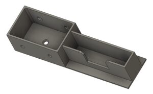
Fusion 360 pictorial view of the tag and battery holderFinal assembly of the battery pack and the tag. The dot on the battery pack is a retaining screw.
In theory this modification should dramatically improve the operational life of the tags between battery changes but time will tell whether it is borne out in practice.
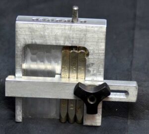
I thought it might be practical to make it as a 3D printed device and with a bit of guesswork came up with a first pass design in Fusion 360. This was based on my set of punches which are 6.4mm square (1/4″) and 58mm long. The design printed in PLA without any problems and the finished punch holder worked fine. It uses one of my printed knobs as mentioned in another post.
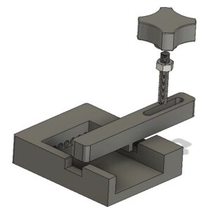
Fusion 360 pictorial view of the finished punch holder
The success led to requests from others who liked the 3D print concept but had different size punches so needed the design tweaked to suit.
This looked like a good excuse to re-familiarise myself with Fusion 360s Parameter functions. In short these allow you to program interrelated dimensions in a design through a series of basic algebraic functions. The end result is a design that is fully flexible on the size of the punches to be used and the number of punches that might be judged needed as the maximum ‘word’ length.
The Fusion file includes the holder, the clamping bar and the knob body. You will need a short length of M6 threaded rod and a M6 nut to finish the knob. The file is configured to 6mm punches, 63mm long but you can edit using Parameters function under Modify. Clearly once you have the Fusion file you could run also run a CAM program and CNC cut the punch holder.
I am afraid this is a Fusion 360 file only. If you aren’t a Fusion user (why not ??) and you want a STEP file creating to your punch sizes then email me and I can run it for you.
As stated in the original article, the kerning of the letters is defined by the punch cross section.