I have made some good progress on taking a PCB design Gerber copper and Excellon drilling files into CNC. I think it is worthy of a full write up but while that gets put together here are some comments.
First of all the conversion process using FlatCAM is very straightforward and I like the fact that you can default save your GCode startup and end routines along with other default settings. Note that I had to scale the drilling data by a factor of 10. Apparently this is not unusual.
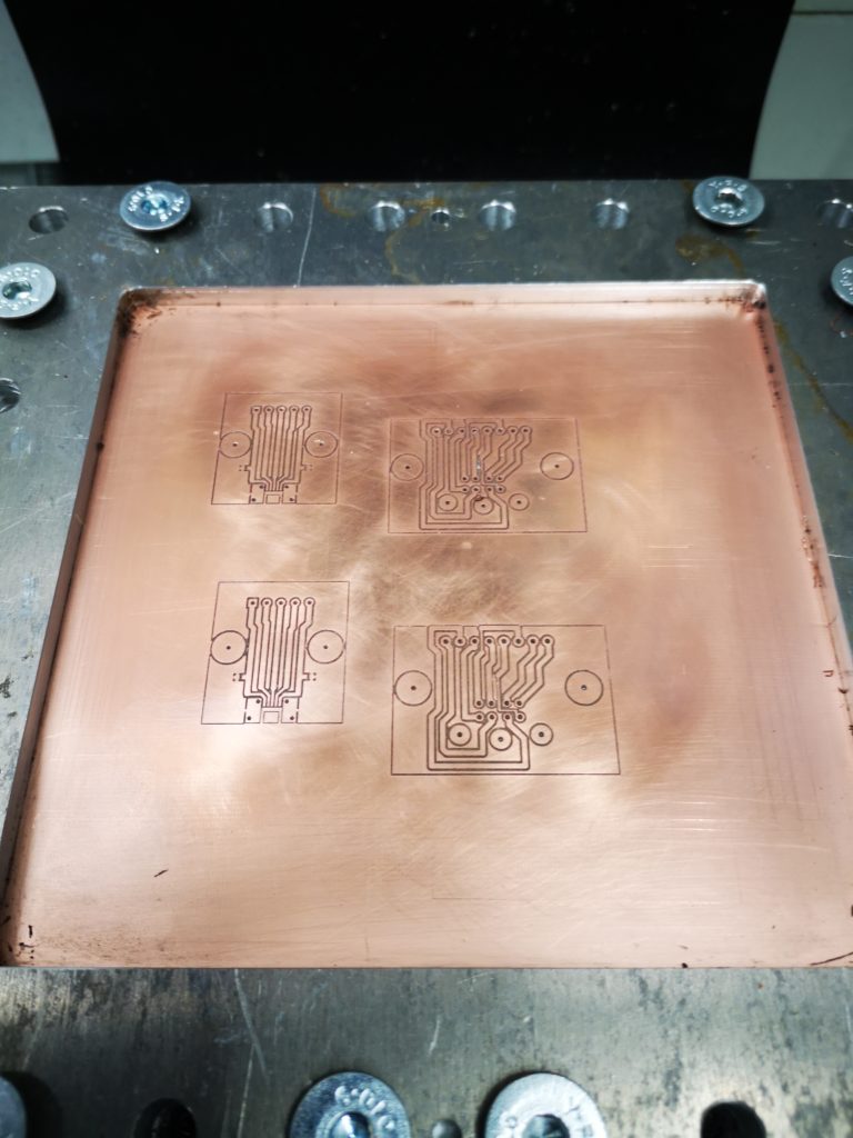
The fun starts once you have code ready to run on the CNC. The board design I was working on was a single sided copper design. Single sided board tends to always have a curvature with the copper on the inside of the curve and the fibre glass outside (if you see what I mean). This is probably the manufacturing process with the copper and its adhesive ‘pulling’ the board.
Double sided PCB tends not to be so bad in this respect and the effect is balanced out by the two coatings. My board was therefore much more bowed than a double sided one. (Incidentally FlatCAM allows for double sided board designs).
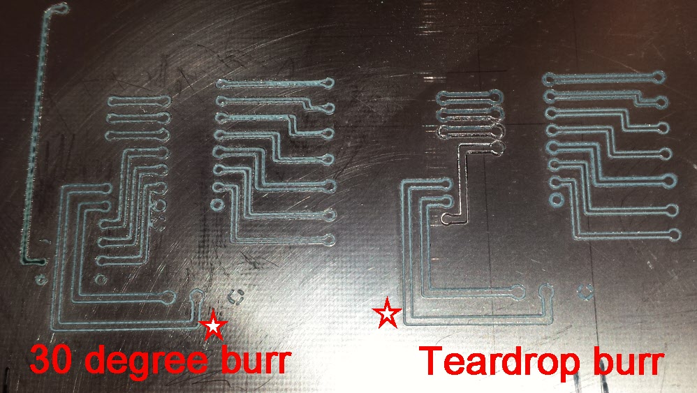
If you think about the geometry of what is going on it is critical to make sure the PCB material is flat on the milling table. The greater the included angle of the milling cutter tip the worse things get if there are variations in surface height. A height variation equates to a widening of the tool cut. See the image below. (Not to scale).

I initially used 6mm MDF as my sacrificial backing board to protect my tooling table. When I checked the MDF for flatness with my Haimer I was disappointed with the result. Increasing the MDF to 12mm made a huge difference and good enough for the purpose. This could have been a different manufactured MDF so the change of size is not definitive.
Initially I clamped the PCB to the MDF with a number of woodscrews around the periphery. On checking with the Haimer this was not good with visible variations that I could impact by pressing on the PCB surface.
Next step was to replace the woodscrews with strips of 10mm square aluminium with a 1.5mm step on one edge. These were screwed to the MDF on all 4 sides of the PCB blank and this dramatically improved the flatness to a point were it was adequate. Pressing the board surface did not change the Haimer readings.

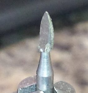
Flatness having been solved I addressed the cutter problem. I had ordered some 10 degree included angle cutters from China but while they were in transit I got to talking with Think & Tinker in the US. They were incredibly helpful and suggested that I should consider a 60 degree included angle cutter with a 5 thou tip. They also suggested I try their lubrication to improve the cut quality and to also help protect the tool from wear. Their tools also come with a fixed collar which means you can change out the cutter without having to reset your Z zero.
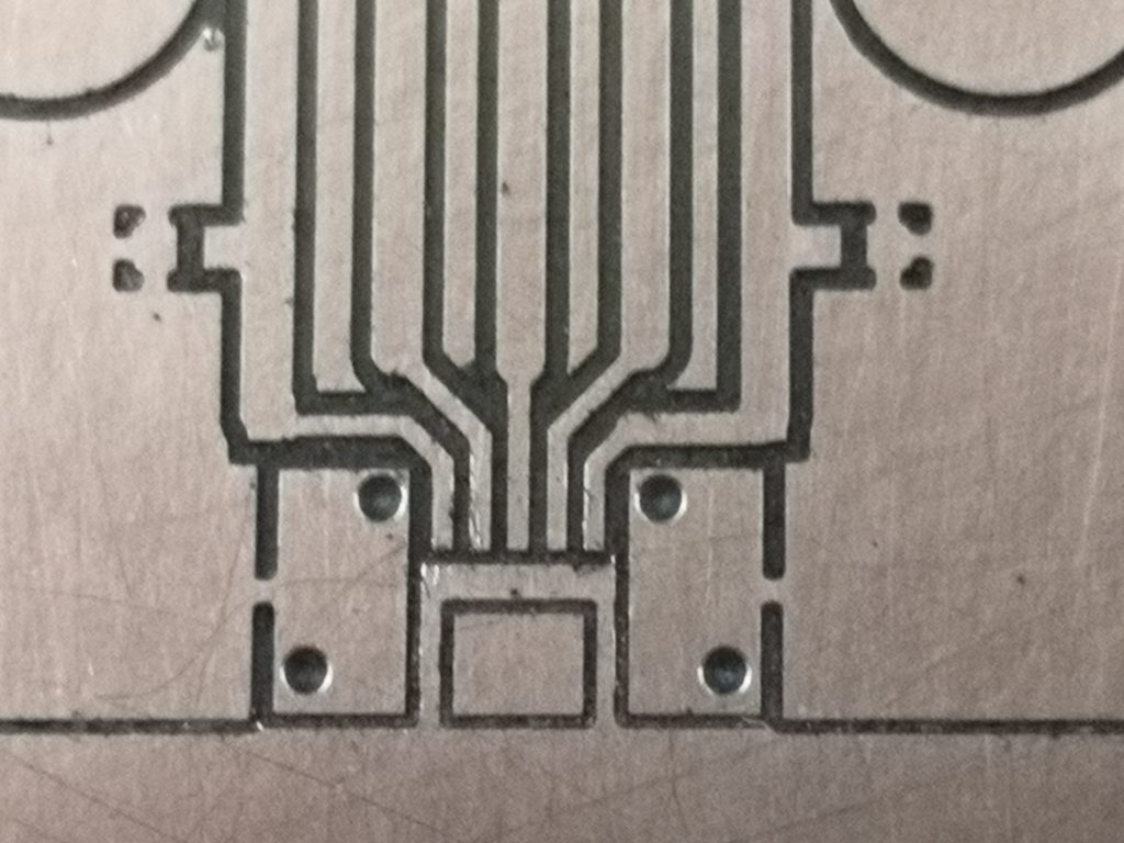
This 60 degree cutter worked a treat and the results were startlingly good. I did not use the lubrication from T&T but instead used my normal FogBuster fluid (QualiChem ExtremeCut 250C) on a gentle repetitive puff. This seemed to work and kept the dust damped as well as improving the cut.
While I could run the spindle at up to 10,000 RPM, I kept it down at 6,000RPM with a cutting speed of 3″ per minute (75mm). I had a Z clearance of 0.1″ and depth of cut of 0.005″. (Sorry for the mixed dimension standards but PCBs tend to be designed in Imperial but I prefer to work in Metric).
After the milling of the copper was complete I drilled all holes at 0.6mm (24 thou) using a carbide drill sourced from Drill Services of Horley (UK). This was simply a change of tool, registering the tool length and loading the drilling GCode produced by FlatCAM. The drilled holes were spot on dead centre in the copper lands.
In closing I would like to say how impressed I have been with the Tormach. I had milled the copper one day and switched off for the night. Next day I switched on the mill and absolute referenced XYZ and put the drilling tool in the spindle and hit go. The holes were smack on dead centre in the lands without having to tweak anything.
It has been an interesting challenge that my friend had set me and he has gone away with a good looking PCB and my knowledge base has improved which is what it is all about.


A more detailed write up to follow.
Similar or related subjects : –


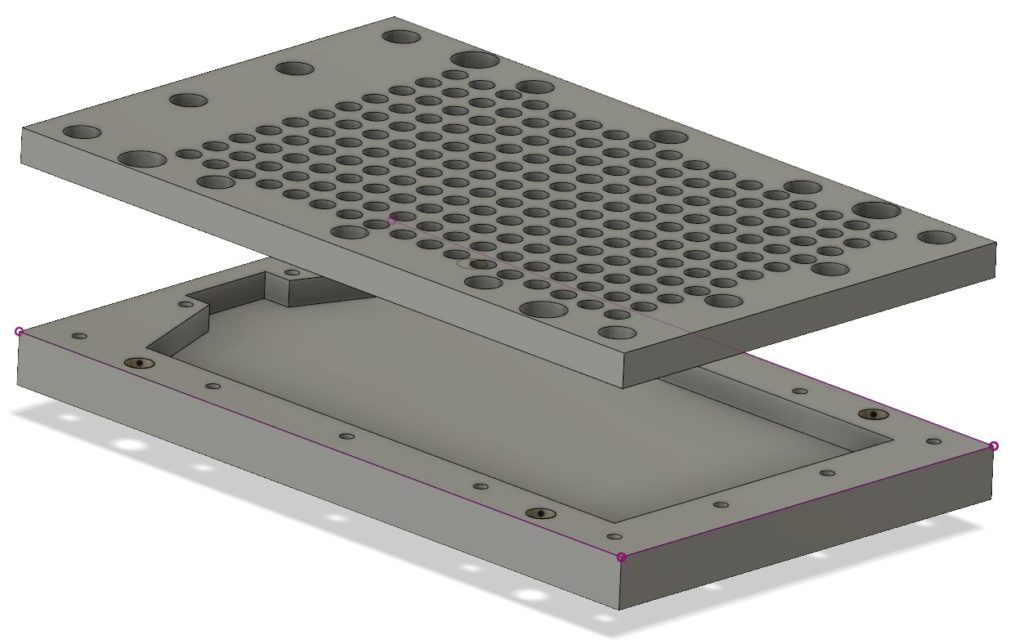
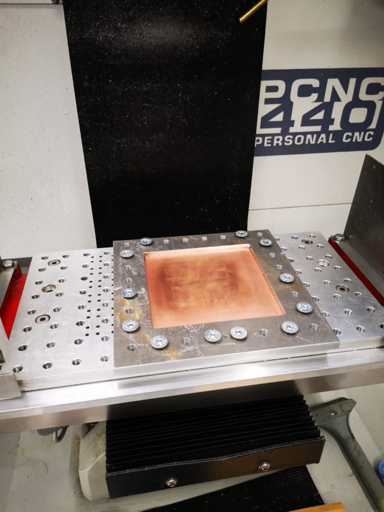
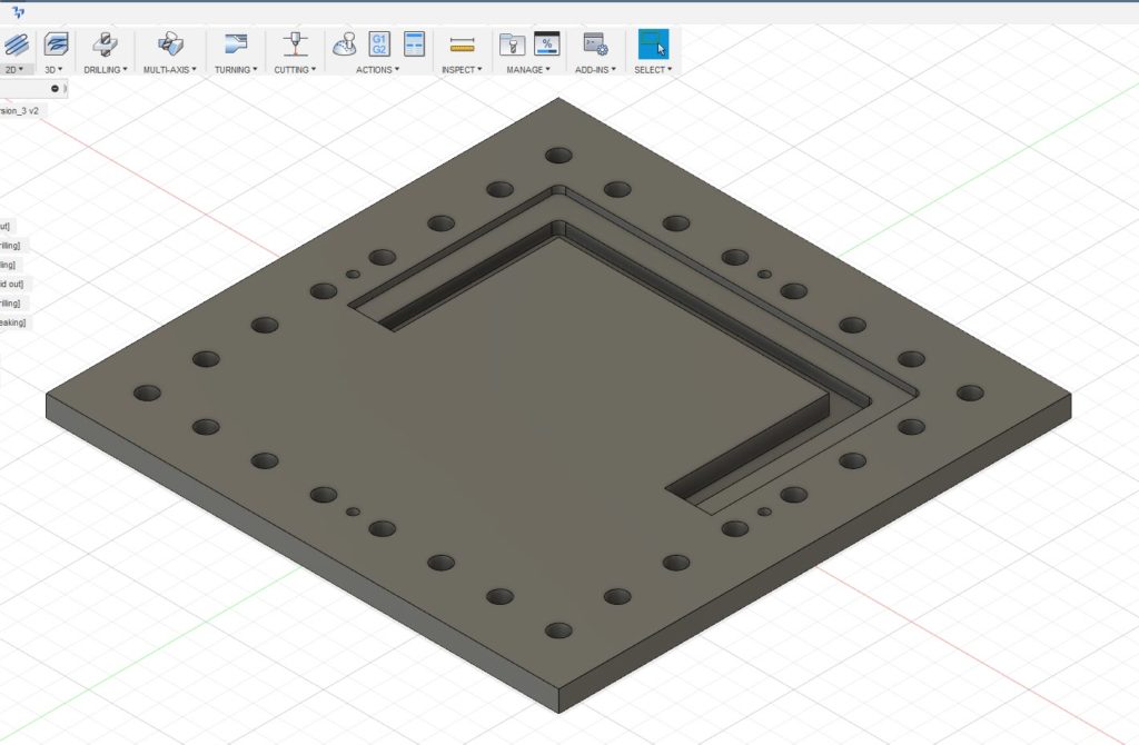 The outer holes are for the M8 clamping to the table and the four smaller holes are the tooling holes. Being tight with my materials I did not want to just mill out the centre of the plate and have a mountain of swarf (chips). Instead I designed it with two slots as shown, one for the clamping surface and one that almost cut through the stock. The partial cut was to ensure the central piece did not flip out once cut free and damage my cutter. First one half was drilled and cut and then the plate was rotated 180 degrees and the second half cut. This left the central island just held in place by less than 0.5mm of material. This was easy to hand cut through to liberate the central area. The plate was then turned over and the cut edge cleaned using the same tooling position and doing the same 180 degree rotation. To my surprise the rotation process on the tooling pins worked very well with only a minor step transition at the overlap point on all cuts. This was probably more down to my 3.7mm tooling pins being not quite concentrically turned from 4mm silver steel. With this finished I now had a much more robust clamp for the PCB material. I had made the clamping step 4mm deep so I could put sacrificial backing boards behind the PCB being run. This would allow drilling through as needed. Checking the flatness of a clamped PCB blank with my Haimer showed variation of a few thou in the top surface of the PCB Z position. The worst case variation in Z was at dead centre where the PCB’s natural bow was most dominant.