There are quite a few entries on my blog regarding using FlatCAM to convert PCB design software manufacturing files into CNC code. I also have mentioned my small home made vacuum table and a floating foot compression device both for holding the PCB blank flat while the milling takes place.
I have revised my original write up to focus on FlatCAM version 8.991 and also pulled together notes on these other techniques. If you like it let me know. If there are mistakes also let me know.
A new idea for keeping PCB material flat while milling artworks
The vacuum plate mentioned elsewhere on my blog serves me well when milling printed circuit boards on the Tormach PCNC440. It keeps the PCB material flat and makes the cut widths repeatable when using V cutters.
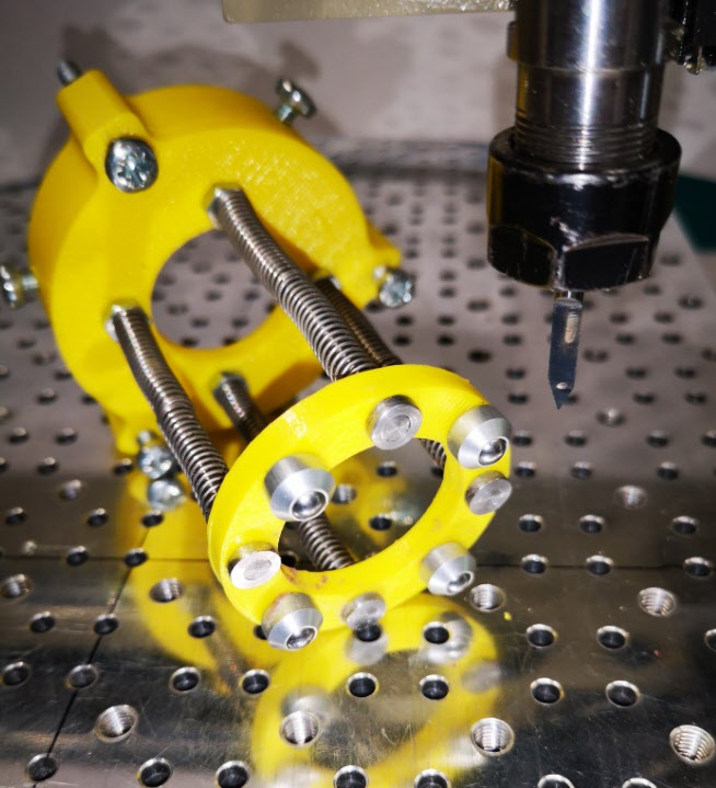
Idle hands and brain during social distancing has produced a possible solution that might be of interest and stimulation to others. It consists of a circular pressure ring that sits around the spindle chuck and tool. There is a second ring that sits on the spindle body connected to the lower ring with rods which have coaxial springs pushing down on the lower ring. The magic is to use mini ball transfer units on the lower ring to press down on the PCB and glide friction free around the PCB as the cutter does its stuff. The assembly is held in place on the spindle with 3 gripping screws. The downward pressure is adjusted by 3 screws that press against the spindle mounting frame.
The ball transfer units come in all sizes and are very common in baggage handling systems at airports and in industrial conveyor systems. The ones I used came from RS and have a 4.8mm ball and a M2 mounting shank.
The prototype was made using 3D printed rings. There is an image below. Apologies for the yellow PLA but finding any PLA at a decent price is very difficult in the present circumstances.
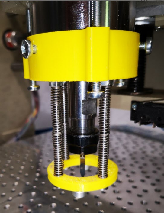
A view of the underside of the lower ring and the four ball transfer units. In the background is the upper ring that sits around the spindle with the pressure adjusting screws and the spindle gripping screws.View of the pressure foot in place on the spindle showing the tension adjusting screws and spindle grip screws
The idea seems to work and has produced some good consistent quality PCB prints. It does have disadvantages in that you need to have a larger PCB blank to allow for the larger footprint of the pressure ring. It is probably only of practical use for PCB milling but then the problem of flatness is less critical in drilling the board and routing the profile.
After a lot of editing I think the attached document will give an in depth understanding of how to use FlatCAM based on Version 8.5. The document is based on our experiences and a steep learning curve. We now have a repeatable process for milling PCBs from Gerber and Excellon files exported from a PCB design package.
The document may well have mistakes and we would appreciate feedback good or bad.
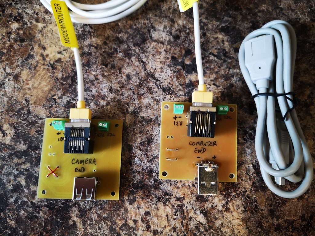
One of our group of ‘silver experimenters’ is building an Arduino based celestial camera tracker. This will be deployed in the garden and he needed all control to be routed back inside the house. The garden installation consists of a USB webcam mounted on a servo controlled platform all powered by 12V DC.
We pondered long on how we might remotely connect to the garden. The crucial thought was that the Arduino servo board was a two wire interface using the I2C format data exchange. Given that the USB needed four wires and the DC supply two wires we had a need for an eight core cable connection. It seemed like a length of CAT5 cable would do the job and we could elegantly use standard CAT5 sockets.
The PCB was designed in Design Spark and milled on the Tormach PCNC440 using FlatCAM.
There is a problem with running USB over more than 5m but I did some tests at 10m and all seemed fine which should be adequate for the application.
The breakout boards had a male and female USB connector fitted and the connections had to ‘cross over’ on one of the breakout boards to maintain continuity. We also paired the Data + and Data – connections with the +5 and Ground twisted pairs in the CAT5 so the Data + and Data – were not twinned together.
Nothing technically magic but a simple solution to a project need.
I & J Arc Code Calculator (with updated spreadsheet)
I had a need to hard code a circular PCB cut out CNC code that would cut four arcs around a milled PCB and leave four breakout tabs to retain the board in place in the blank until the job was finished.
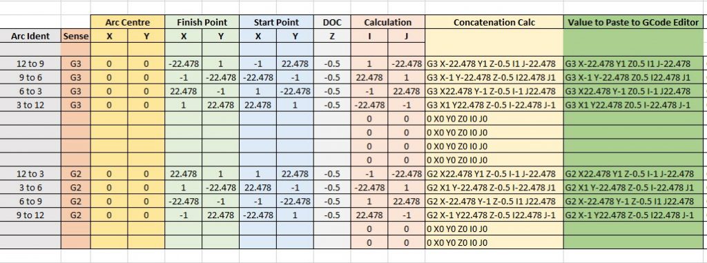
To create I & J codes you need to know the start point, end point and radius of the arc. The end point becomes the X and Y. The delta X and Y location relative to the radius centre point X and Y becomes the I and J values. You can also add a depth of cut value for Z as part of the block. Note that the Arc is assumed to run anticlockwise when using a G3 code running from start point to finish point. Use G2 if you want a clockwise motion. The principle is the same with both rotations.
You end up with a block code of the format G3 (G2) Xa Yb Zc Id Je where a,b,c,d,e are the coordinate values. I found that working with positive and negative values when trying to find the I and J values relative to the centre was hurting my brain. A spreadsheet was needed …..
Screen shot of I and J calculator spreadsheet for G2 and G3 coding with examples based on CW and ACW arcs around quarters of a circle with small gaps between each arc.
You can download the sheet as a ZIP file from the link below.