Using Raaco section boxes for fastener storage

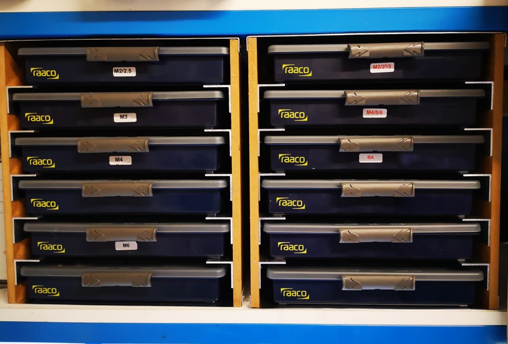
I am a great lover of the Raaco 18 section storage boxes for my various sizes and ranges of nut and bolt fasteners.   These boxes are not unduly expensive and are very durable with a sliding locking latch (assuming you don’t forget to slide it place – see below). 


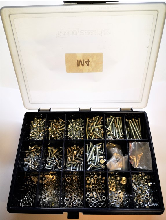
To date these boxes have been stowed stacked one of top of the other on the shelf above my office workbench.   Come the need to get a particular size fastener for a job I can bet on the box I need to access being at the bottom of the stack.   This can get frustrating and can also be risky because if I haven’t fastened the lid properly there is an ever present possibility of a lot of fasteners hitting the floor with some associated colourful expletives.

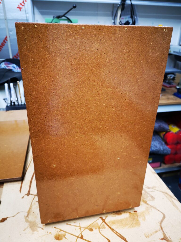
As you have probably gathered from the previous post, this has been woodwork week or at least MDF week if that counts as real woodworking.  After finishing the storage box for my clock bushing gizzmo I still had MDF to spare. With some judicious juggling in Fusion 360, I came up with a design for a slide in storage rack for my Raaco box collection.   In fact there was enough MDF left over to make two of these.   I did have to buy in some 30mm x 2mm angle though. The design allows access to any fastener box without the need to shuffle the stack to get at the one I needed.  Joy of joys.

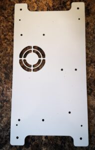
The storage unit is 300mm high and has MDF sides and back board.  I had to revert to a 1mm sheet of  aluminium for the top and bottom surfaces to get the optimum number of boxes to fit between the workshop shelves.   Each storage slot has an aperture of 250mm x 47mm (excluding the aluminium angle) and is 180mm deep.

The added bonus to the design is that the Raaco fastener slide is a very tactile grab handle to draw the wanted box out of the rack.  The feel of the slide also acts as a warning flag that the slide might not be correctly locked in place.

Yes I know it is all a bit anal.   Making things to make things etc but less frustration means more productivity … well that’s the theory.

Similar or related subjects : –

Bamboo barbeque sticks as dowels

OK so this is nothing radical but worth adding to the armoury.  

I am in the process of making a protective box for my clock bushing tool and the various accessories that are used with it.   I had some 9mm MDF board in stock that looked a potential candidate for this.   The only problem with a 9mm board thickness is that this didn’t leave much margin for error using standard 6mm dowels and I did not want to use screws or nails to hold my box together.

The solution I came up with was to use 3mm bamboo barbeque sticks as dowel substitutes. These are incredibly strong in sub 25mm lengths.

I did cheat however and did not try fit them in blind holes but instead drilled the mounting holes through to the outside surface.   It still looks OK and has resulted in a very strong structure.

Using barbeque sticks as dowels
Image of the side panel of my home made clock bushing tool protective box. This shows the bamboo barbeque stick dowels bonding into the edge of the 9mm MDF components (the ‘dowels’ can be seen as white dots along the top and bottom edge).   The MDF is finished with Yachting Varnish.  You can see what a messy painter I am ….

Similar or related subjects : –

Clock adjuster rod for measuring spring and fusee drive power

 I was presented with a clock that seemed to be low on drive power and it was proving difficult to diagnose where the fault lay. I remembered seeing articles by both William Smith and John Wilding about a device that could give a relative measure of the drive power from the fusee.  There is also a brief mention of this in Donald de Carle’s – Practical Clock Repairing.

This will be difficult to describe but in essence it is an adjustable balancing rod that is mounted on the fusee winding square.  The movement’s centre wheel and second wheel are left in place but the escapement is removed.   The rod has a sliding weight that can be adjusted to counter the drive power from the spring through the fusee chain to the fusee itself.    By winding the fusee one step at a time and resetting and noting the counter weight position it is possible to derive a graph of fusee turns against drive power.  Here is a pictorial view of the device and below that a picture of my version.

A sketch of the principle of the balance rod for fusee drive checking
Image of my version of the balance rod
My version of the balance rod. The winding socket is interchangeable for different fusee square sizes.

William Smith suggested making the mass of the sliding weight equal to 1lb and measuring the weight position in inches from the balance centre to the centre of the weight.   This results in a graph of drive in lbs/inches.

In practice the balance point is a little subjective to set.   You need to move the weight back and forth such that the rod remains horizontally balanced against the drive from the fusee square.  Once a balance point is achieved the distance from the moveable weight centre to the winding axis centre is recorded.

On this particular clock I plotted the results of the each turn of the full wind range of the fusee and the balance distance seemed to be reasonably repeatable and overall fairly flat. This suggested that perhaps there was not an individual fusee positional problem but something that was common mode across the range of the winding.   To me this indicated that the drive transfer through the centre wheel and the second wheel was potentially the issue.

Checking the arbors against the plate pivots did not reveal a great deal of wear but on dismantling and checking more closely one of the centre wheel pivots had a worn curved profile.   I re-made the pivot and re-bushed the plate and reassembled the movement. On re-running the test with the rod I found I had gained an extra 1″ movement of the balance weight along the rod.  This suggested that more power was now being transmitted to the train, that is the train was not presenting such a high resistance to motion and more power was being created to drive the clock.  

This appeared to solve the problem with the clock having a much stronger beat.   This result is indicative of the value of this simple tool.

William Smith also suggests that the balance rod is useful as a temporary drive source.  Suppose you have a clock stripped down and want to quickly check the train.  Without fitting the barrel and fusee chain, the balance rod and balance weight can be mounted on the fusee square to provide quite a few minutes of drive to quickly exercise the train without having to undertake a full movement rebuild.

Similar or related subjects : –

Experiences CNC machining Aluminium Composite Material (ACM)

I had a recent request to machine some panels in 3mm thick ACM.   This has a polyethylene core sandwiched and bonded between two thin sheets of aluminium.   The sizes of the various panels requested could not be easily accommodated on my Tormach PCNC440 CNC mill so I had to dust off my CNCEST 3040T baby router.   Five out of the six panels would fit inside the 3040 working footprint but the sixth required me to revert to a two setup movement of the workpiece in the Y axis.  My write up of this stepping process for oversize objects can be read here.

The CNCEST 3040 has a maximum spindle speed of 10k RPM and is controlled using Mach3 with all the frustrations that brings to the party plus manual tool changes etc etc.

I received DXF drawings of the panels and these were imported into Fusion where they were simply extruded to 3mm before processing in Fusion Manufacturing.  Each CAM operation was exported as a separate function into Mach3 regardless of tool changes.  This gave me step by step control.

I used a 12mm thick MDF sacrificial (spoil) backing board to mount the panels.  As all the panels were of the same general dimensions this made mounting the panels a repeatable process using a fixed matrix of woodscrews into the MDF.  The 12mm depth of the mounting board made the tooling pin reference holes for the Y move much more rigidly fixed and as a result more repeatable to use.

The main problem encountered was that the ACM does not readily adapt to machining with conventional end mill cutters.   I tried using my stock 2 flute parts and these would skim on the top aluminium surface while the plastic underneath deformed to the Z axis increasing pressure.   Once sufficient pressure was exerted the tool would finally bite into the aluminium and punch through into the plastic with a noticeable ‘clunk’.  This played all sorts of havoc with the Z axis height referencing and also lead at one stage to the Z axis stepper coupling working lose.

The solution was to go to a single flute spiral cutter style. These were purchased from APT Tools (UK supplier).  Hot knife through butter comes to mind with the result of this change.

Single flute spiral end mill from APT Tooling UK
The single flute spiral end mill from APT Tooling UK

For straightforward hole cutting I used standard PCB carbide drill bits from Drill Services (UK supplier).  These are nice to use as all have a standard 1/8″ shank which makes tool changing a little bit easier.

Once all these frustrations were overcome the process became much more repeatable albeit with one or two curved balls due to Mach3 lock ups.  Have you ever enjoyed trying to manually re-reference a half finished job ? …..

The finished largest panel that required a two step movement in Y axis

More accumulated knowledge gained and lots of black plastic swarf (chips) to clean up before it could migrate everywhere into the house.

Similar or related subjects : –

Spreadsheet Compendium by Popular Request

I have had a few requests for a compendium of all my spreadsheets created over the months and years.   This will be a work in progress as new sheets are created and then added.   Here are the current contents.   

A collection of my popular spreadsheets

Click on the link below to download the ZIP file.

Spreadsheets Compendium Jan 2022

Similar or related subjects : –

Verified by ExactMetrics