Lempor Modification to my Poly V
This post was corrupted when converting from Classic Editor to the new Block Editor and has been re-created.
I have made mention of my Poly V 5″ gauge live steam locomotive elsewhere on my blog. With lockdown having restricted running the engine on the Club track, the loco has sat idle in the workshop.
The locomotive has always been a struggle to maintain steam over a full running day. It starts off enthusiastically but then begins to struggle. This is frustrating and also embarrassing when I have to push it round to the steaming bay.
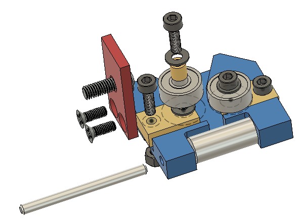
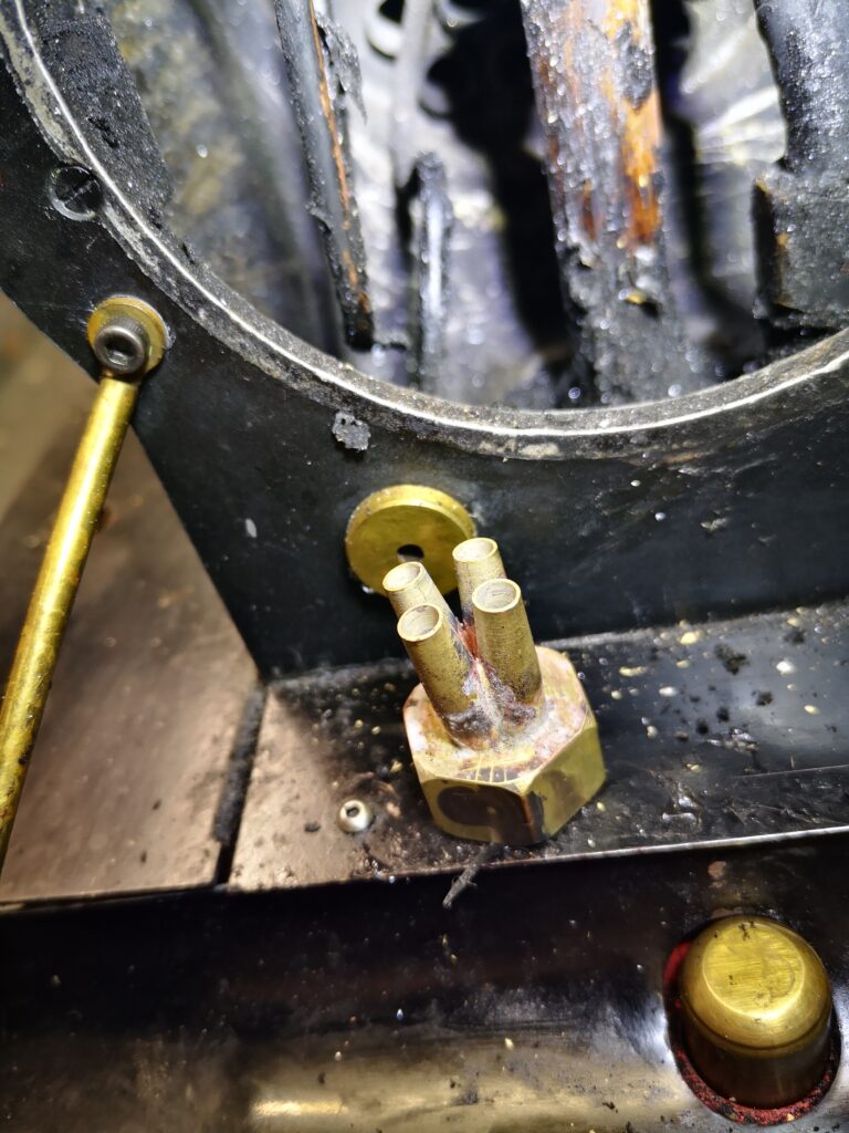
I was sent some notes on Lempor Draughting to change the blast characteristics in the smoke box. With time on my hands I spent some time on Fusion 360 drawing up a possible Lempor assembly. This is shown below. It consists of four nozzles each having a cumulative aperture area equal to the original blast nozzle as fitted in the Poly V.

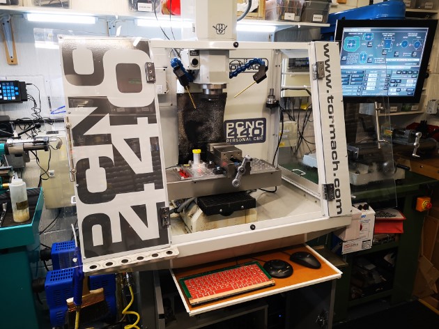
The assembly was quite tricky. I bought in a new standard nozzle from Poly and then modelled it and the new sub nozzles in Fusion 360 to create the toolpath to mill out on the CNC, The new nozzles were created on the lathe and the mating butt flats machined on them in the mill. It was very fiddly. I wired them together and silver soldered them in place. Here is a picture of the finished assembly before fitting.
Because the new blast is diverging I had to increase the height of the petticoat. I did this experimentally by fitting a small grub screw at the back of the smoke stack to grip the petticoat as I moved it up and down. This resulted in the petticoat being almost at its maximum height. One idea suggested by a club member was to make this adjustment on a cold morning with the smoke box door open so you can see the blast pattern.
My subjective conclusion is that the engine now steams from cold much quicker and it runs very well (providing I keep the fire level high in the firebox….). Whether this is the new blast pipe or the Rosebud grate or the coal or a combination of all three is difficult to judge. It is certainly a different engine and a pleasure to drive.
Links to similar or related post are listed below : –
- Model Railway Track Testing Monitor
- Swiss Vapeur Parc Festival Week
- 3D Printed Jigs to the rescue
- Rosebud Fire Grate on a Silvercrest BR Class 4
- Simple Water Level Sensor for Live Steam Locos
- French Model Steam Engine Gathering
- Replacement Whistle on Polly V Steam Engine
- Bad day steaming with my 5″ Polly V live steam locomotive
- Lempor Nozzle added to Poly V 5″ steam locomotive
- Setting up the timing on a Polly V locomotive