I have a Record #34 vice. It has a seriously chunky tommy bar. If you accidently let this drop with a finger in the way you are heading for expletives and a large blood blister.
The fix is to force two O rings over the end stops to act as buffer protection. Apart from lowering your blood pressure and saving your stock of BandAids it reduces the clunk when the bar drops with or without your skin in the way.
Links to similar or related post are listed below : –
When the Arduino Giga appeared on the market with its associated glossy Display Shield it looked like a programmers dream.
I am not a programmer. Sitting down to do a software project to me is like writing off a large lump of my remaining MTBF.
John, my close friend in France, is an also ran in this respect. We both fumble around doing cut, paste and edit development and end up with some quasi stable code that might do the job intended.
So joy of joys the Giga appeared and John got excited … which rapidly degenerated into acute frustration, hair pulling and suicide by software tendencies.
I got sucked in to help – blind leading the blind.
I tried running all the Arduino demos for the Giga Display Shield and after an inordinate length of my life had passed I concluded that any sketch with ‘#Include lvgl.h’ in it would be unlikely to run.
Slight digression. What is not made generally clear is that with lvgl library you have to edit the lv_conf_template.h file and re-save it in the Libraries folder as lv_conf.h. The edit is simply to change a 0 to a 1 and instructions are in the text at the top of the file listing. This edit enables lvgl. I spotted this and duly did as directed. Still no joy.
Out of desperation I deleted the lvgl library version 9.0.0 and replaced it with the 8.3.11 version. I then had to do the 0 to 1 and do the Save As etc routine again….
To my huge surprise this worked . See below as a simplistic overview of the changes needed.
So progress has been made and there are some nice demos to watch now that they are running OK. Note that the Arduino IDE will constantly tell you there is a later version of the lgvl library but you have to ignore this and opt for manual update. If 9.0.0 does get loaded you will have to go through the above process again to the extent of removing 9.0.0 and replacing with 8.3.11 but the edited lv_conf.h file will be unaffected so you don’t have to repeat the edit and Save As process … hopefully someone will fix it in the near future.
I would further add that not all the published demo sketches work. If you want a reliable sketch to demonstrate the camera onto the Giga screen download from Kurt’s depository on the link below.
This is the final offering … well, for the time being ….
I have been slowly evolving my ideas for fume filtering when using the Qidi X-Smart 3 printer. I should say there is nothing majorly wrong with the fan system as shipped but there always seems to be background residual fumes even when printing PLA. The level of fumes does seem to be dependent on the brand of PLA used.
The rear fan as shipped has no HEPA filtering, it simply vents the chamber into the external air. This fan only comes on during the printing process.
I have previously posted some early ideas for improving this using readily available HEPA filters. Following some discussion with Christian, a fellow X Smart user, we worked together to evolve this further.
The first phase was to upgrade my external fan filter duct design to have both HEPA and a carbon granule filter sections. The carbon granules are sandwiched between two 10 gauge stainless steel meshes and an outer cover holds everything in place.
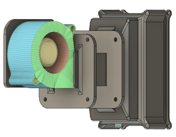
The result of this looked promising but the axial fan as shipped lacked a decent air flow through the filter stack. This was upgraded to a 6028 centrifugal fan mounted on an adapter plate. The Fusion 360 assembly is shown below.
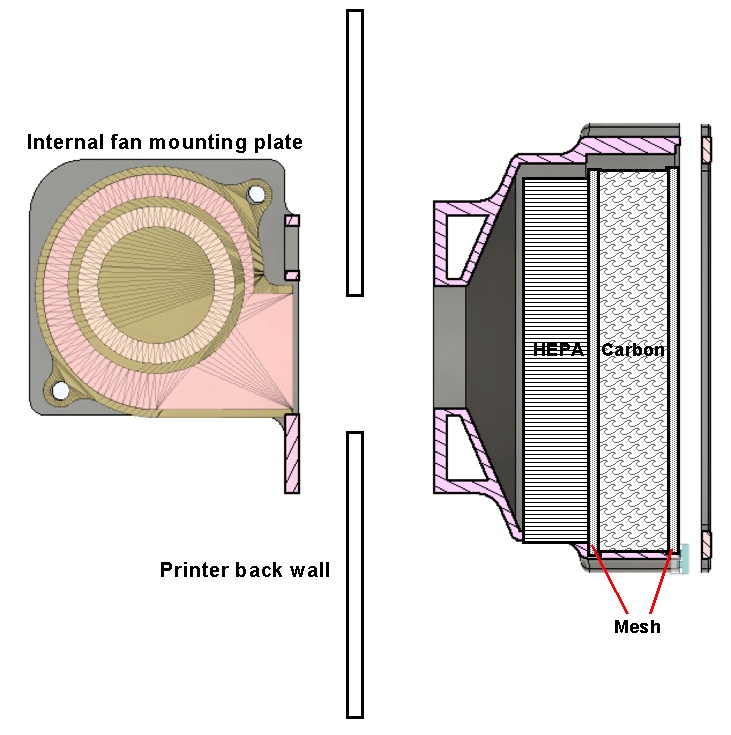
Below is a simplified cross section view. The internal fan adapter plate flange and the external filter stack are bolted together through the back wall of the printer using the original fan mounting holes and M3 screws and nuts. The fan is mounted on the adapter plate using M4 screws and nuts. There are moulded nut cavities to make assembly easier. The cover plate which holds the two meshes and carbon granules in place uses M3 screws into 3D modelled threads in the corner holes.
As previously posted I had fitted a full size Bento filter to my Qidi ifast. Further discussion with Christian revealed he had fitted the Bento Mini to his X Smart and seemed impressed by the internal air scrubbing action. I looked at the design of the Mini and after some thought changed the carbon cavity filtering walls from a printed grid to using the same 10 gauge stainless steel mesh as used above. The Bento Mini printed well and I was impressed by the thought that had been put into the design. There is a version with a hanging bracket designed for the X Smart 3.
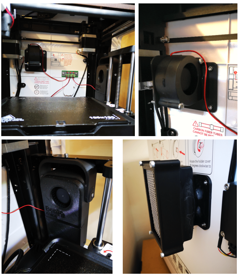
I now had a belt and braces solution – the Bento for internal scrubbing and the HEPA/Carbon filter pod on the rear extract fan. Here are some images of all the components in place and the small terminal strip to interconnect the 24V supply.
The fans used on both assemblies are the same dual bearing 6028 models as detailed in the Bento write up. These are rated at 24V @ 80mA. The axial fan originally fitted was rated at 130mA. I removed the original fan and wired the Bento and the extract fan in parallel and connected this to the original supply feed from the control board via a small terminal strip. The two fans are only commanded ON during printing.
That is my hopefully my last solution but as ever it will depend on actual performance to see whether I notice the difference in air quality. Mission creep is always possible.
As mentioned in a previous post, I designed some booster feet to fit over the existing feet on the printer. These increase the air gap below the printer to allow more air flow. If you print them in TPU they gave extra stability to the printer and reduce resonances.
Here is a link to the STL files and write ups for the simple duct, the fan adapter plate, the two stage filter duct, booster foot and also the modified Bento carbon box and lid with mesh divider walls. Note of late I have been printing with a setting of four perimeters which gives stronger modelled threads.
Thanks again to Christian in Germany who has been a great help in bringing these various mods to fruition.
James Browning does not have a website. You send him an email to the address below and he sends you the details of his product. Note that you need to copy his address into your messaging app as the link below is an image not a URL. This affords him some protection against spam.
Installation of James’ box is straightforward with copious notes and videos to assist. Connections are simple – +12V, 0V and the two old wires originally going to the mechanical pump. You need to route the fuel feed via his box and then before running the heater you need to bleed the air from the pipework. There is a handy little switch in the box to help do this.
There is a knob on the box that alters the fuel mix which you can tweak with altitude. This is relevant if you are touring in a mobile home but not for my installation heating the workshop. The box as delivered has the fuel mix set to sea level operation and as I am at 90m asl I left it untouched.
So what have I noticed ?
First of all the old ticking noise has gone and the burner noise is more even. Major plus.
With the mechanical pump I had to put a metal plate against the wall to stop the soot staining the brickwork. Clearly the burn as it was was not correctly balanced to have caused this. With the new electronic pump all I have is condensation dribbling down the plate (it is freezing cold outside) so the burn is more efficient.
I can now burn our domestic heating oil (kero) as the fuel does not need to have any lubrication content as it did for the mechanical pump. Currently in the UK domestic heating oil is around GBP0.70 per litre and road diesel is GBP1.60 so a direct net saving amortising the cost of James’ unit.
Conclusion therefore : -no ticking, more efficient burn, lower cost fuel leading to an overall fast investment return and ultimately a net saving.
So far I am very pleased with the upgrade to my heater and I wish James every success with his innovation.
Links to similar or related post are listed below : –
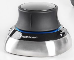
It is sometime since I looked at the SpaceMouse programmable menu options for Fusion 360. I only have two programmable buttons on my mine. I don’t think my brain is now capable of retaining any more than two button options. I struggle just remembering the keyboard shortcuts beyond Extrude and Dimension. The left SpaceMouse button I have set to reset the ISO ‘home’ view and the right hand one was set to the ‘change views’ pallet.
I recently upgraded my SpaceMouse driver to 10.8.17 and on checking the Fusion 360 button options I see there is now one for directly triggering the 3D print sub menu. There also seemed to be far more button options which I don’t remember seeing there before. As a result I have now reset my right button to initiate 3D print. The question is will I remember it is there ?
If you are a Fusion 360 user and haven’t got a SpaceMouse you are missing out on a whole new world of Fusion efficiency. It is a joy to use and does not take long to learn to manipulate. You could drop a hint for Christmas …. or you could look on EBay where there are lots for sale. Why people are selling them beats me.
Links to similar or related post are listed below : –