I was presented with a clock that seemed to be low on drive power and it was proving difficult to diagnose where the fault lay. I remembered seeing articles by both William Smith and John Wilding about a device that could give a relative measure of the drive power from the fusee. There is also a brief mention of this in Donald de Carle’s – Practical Clock Repairing.
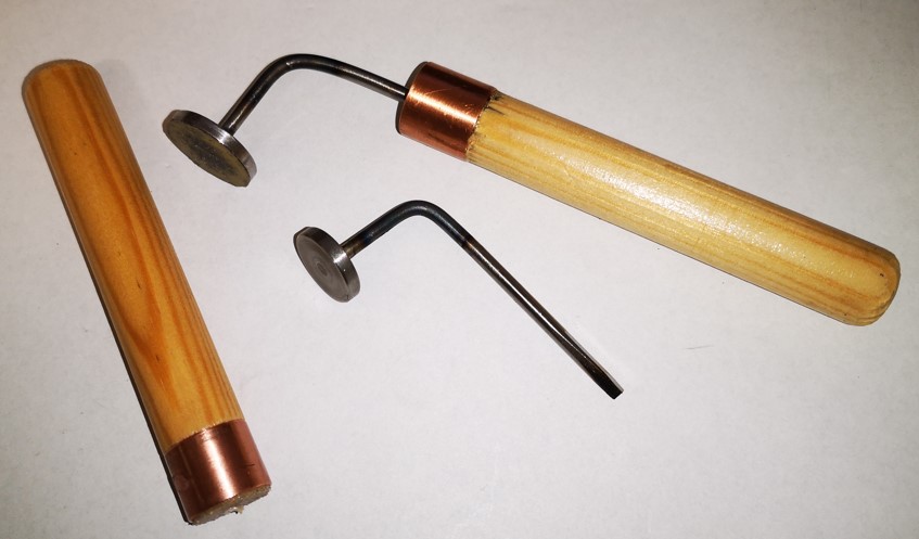
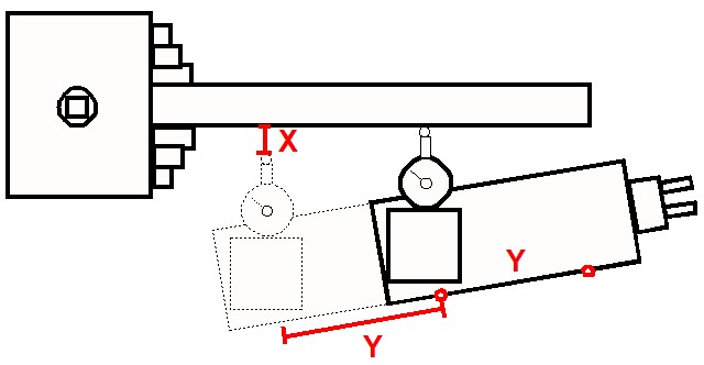
This will be difficult to describe but in essence it is an adjustable balancing rod that is mounted on the fusee winding square. The movement’s centre wheel and second wheel are left in place but the escapement is removed. The rod has a sliding weight that can be adjusted to counter the drive power from the spring through the fusee chain to the fusee itself. By winding the fusee one step at a time and resetting and noting the counter weight position it is possible to derive a graph of fusee turns against drive power. Here is a pictorial view of the device and below that a picture of my version.


William Smith suggested making the mass of the sliding weight equal to 1lb and measuring the weight position in inches from the balance centre to the centre of the weight. This results in a graph of drive in lbs/inches.
In practice the balance point is a little subjective to set. You need to move the weight back and forth such that the rod remains horizontally balanced against the drive from the fusee square. Once a balance point is achieved the distance from the moveable weight centre to the winding axis centre is recorded.
On this particular clock I plotted the results of the each turn of the full wind range of the fusee and the balance distance seemed to be reasonably repeatable and overall fairly flat. This suggested that perhaps there was not an individual fusee positional problem but something that was common mode across the range of the winding. To me this indicated that the drive transfer through the centre wheel and the second wheel was potentially the issue.
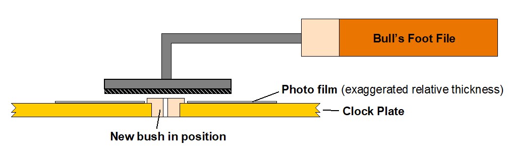
Checking the arbors against the plate pivots did not reveal a great deal of wear but on dismantling and checking more closely one of the centre wheel pivots had a worn curved profile. I re-made the pivot and re-bushed the plate and reassembled the movement. On re-running the test with the rod I found I had gained an extra 1″ movement of the balance weight along the rod. This suggested that more power was now being transmitted to the train, that is the train was not presenting such a high resistance to motion and more power was being created to drive the clock.
This appeared to solve the problem with the clock having a much stronger beat. This result is indicative of the value of this simple tool.
William Smith also suggests that the balance rod is useful as a temporary drive source. Suppose you have a clock stripped down and want to quickly check the train. Without fitting the barrel and fusee chain, the balance rod and balance weight can be mounted on the fusee square to provide quite a few minutes of drive to quickly exercise the train without having to undertake a full movement rebuild.
Similar or related subjects : –
- Arduino Processor Reference Clock Accuracy
- 3D Printed Length Gauge for In Barrel Mainsprings
- The “Modern Clock” by Goodrich
- Microset Timer interface using Fusion 360 3D model with Fusion Electrical
- Clock adjuster rod for measuring spring and fusee drive power
- Update notes on modifications to the Devon Sea Clock
- A church clock problem and lockdown timekeeping
- Repairs to an ancient Thwaites clock completed
- Further 3D printed soft jaws for the Thwaites clock escape wheel
- Vice soft jaws and then soft soft vice jaws