This one is way off beam …. an enquiry for help appeared on the Model Engineering Workshop forum for a simple shopping list when buying groceries etc.
Excel has a facility to create a special version of a spreadsheet called a pivot table. In short this is a table that contains columns and lines but each column has a header that is automated to allow sorting of the table by that particular column. Not only does the column sort the full table but you can refine the data to just show and sort lines of interest. It is easy to use, no macro skills needed just click and sort. I love pivot tables …. well lets be honest I love Excel. So many possible uses for lines and columns.
The spreadsheet is on my download page and is stored as a ZIP file.
The table allows you to have multiple entries for the same produce from different stores and for each store there is a location in the store and a price for the item in that store. So you can have different sorts of bread from different stores and all at different prices. To go shopping you put a ‘Y’ in the Buy column. Here is a screenshot (with random pricing I entered to try it out).
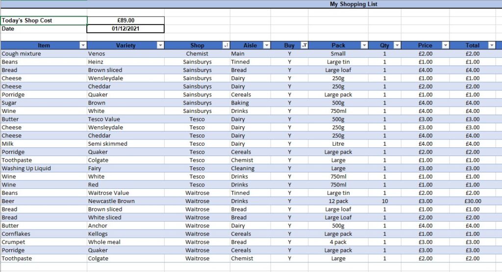
Once you have the ‘Y’ on the items of interest you get a price for the total shop. You can then click on the Buy column header down arrow and a dialogue box comes up that asks how you want to sort. By selecting just the Y entries you get a unique list for today’s shop. Once you have the Ys only, you can then sub sort by store and by aisle or location in the store. Once you have something that suits your expedition, print the active area by highlighting and using Print Selection and off you go with a prompt of what you should be looking for as you walk round each store.
There are no macros, no complex formula and anyone can use it.
OK it is a bit over the top for shopping but as the years pass we tend to forget what we went to the shops for in the first place. We also tend not to see the price creep from week to week. Maybe it will help someone ?
More importantly the pivot table could be modified to become a workshop asset register. Change the headings to Item, Manufacturer, Source, Location, Price Paid (the price you paid or the price you told your wife you paid ?) etc and you begin to look organised. The grim reaper arrives and your family now have a listing of what you had hidden away, where precisely and at what value. They are now a step ahead and they are less likely to get ripped off by the workshop clearance bandits. Think about it, it could be time well spent.
Similar or related subjects : –
- A poor man’s ring gauge set
- Error Code A9 on Odealis Gas Boiler
- Power banks that go to sleep with low current drain
- GyroCut versatile scalpel replacement
- Dry lining wall fastener fixing aid
- Simple Vice tommy bar modification
- Soldering Iron bit storage on Lytool soldering station
- Water Softener goes AWOL
- Noga External Deburrer and Cut Screws
- Technoline Wireless Weather Station problem