

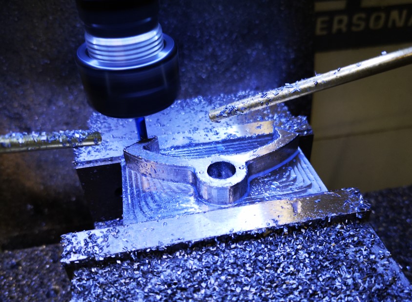
Fogbusters Everywhere
Apart from working on the Thwaites clock parts, I have also done an upgrade to the mounting of my Fogbuster coolant nozzle installation on my Tormach 440. This was triggered after viewing and being impressed by Clough42’s idea. The Fogbuster is a great way to clear swarf and apply coolant. The Fogbuster is normally supplied with a magnetic mounting arm but James’ modification uses LocLine gooseneck components to provide a much more flexible ‘aiming’ capability.
Something to be aware of – James recommends a download from GrabCAD for the 3D files of the two halves of the nozzle holder. These had been uploaded by contributor Br BRB. These were apparently publicly available via GrabCAD. James slightly modified these and was offering them as a free download from his Thingiverse folder. He has since had to remove them for download due to commercial issues. BrBRB has also removed the original files from GrabCAD and is seeking to sell these as finished items. I was lucky to have downloaded the files before the politics cropped up. I still have the downloads.
James also advocates fitting a second identical nozzle to the Fogbuster to avoid coolant and air shadowing. I contacted Fogbuster in California and a very helpful lady called Rachel organised an upgrade kit to provide a second feed from my existing coolant reservoir.
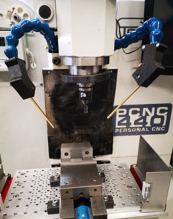
It turned out Rachel was from Bristol UK so it is a small world and we had a good chat. I have fitted both nozzles to the Tormach. With a pressure of around 10 to 15 psi, the reservoir feeds both nozzles very well and is a huge improvement in use.
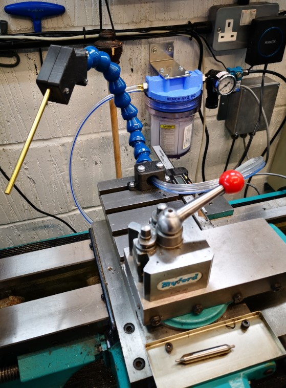
As I was facing a shipping charge from the US I figured I might as well top up the package so I have also splashed out on a baby version of the Fogbuster to fit to my Myford lathe. This uses the same idea but with slightly different mounting that fits into the T Slot on the Myford saddle. I already had the 3D model of the T Slot strip from the ‘bits tray’ installation.
UPDATE : – I went to a Plan B on the lathe mounting – see later post
Another pair of incremental asset improvements successfully installed. I suppose I had better get on and make something now.
Back to ‘the clock’ …
UPDATE 2 : – The 3D printed ball joint kept working lose on both the milling machine fogbuster mouunts. The more I tightened the screws to grip it tighter, the more the 3D components began to crack and give way. The solution was to fit brass inserts into the 3D prints. Problem solved. Incidentally there is a good review of such inserts on CNC Kitchen.
Similar or related subjects : –
- Small handheld vacuum cleaner
- Eccentric Engineering Turnado freehand turning tool
- Rotring 300 2mm clutch pencil modification
- Kindling Cracker – a safer option
- SINO SDS2MS DRO repair
- A useful Amazon sourced small item storage system
- 3D Printed Threads Modelled in Fusion 360
- Three axis stepper controller PCB in stock
- Myford Super 7 Large Bore depth stop
- Tangential Lathe Toolholder for Myford Super 7
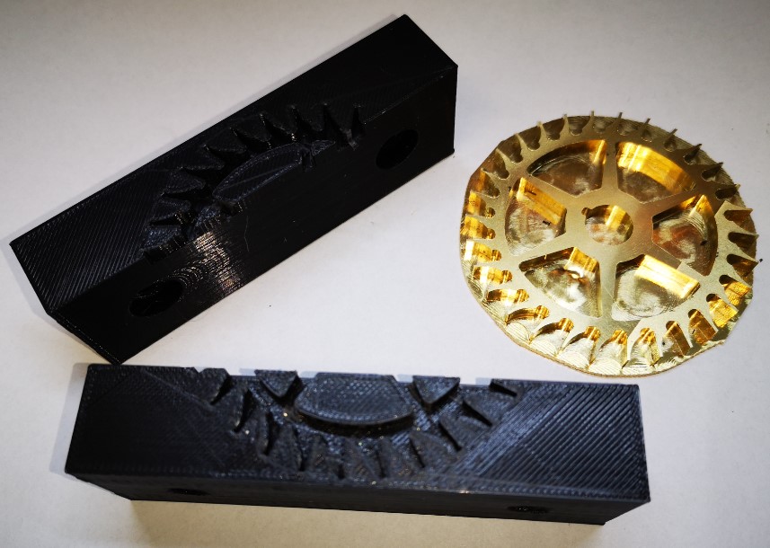
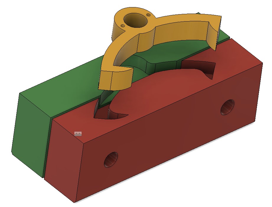

 With hindsight the large pulley could be 3D printed by leaving the rear face completely flat rather than having a profile like the front face.