CNCEST 3040T CNC Router Update

Mach3, Limit Switches and First Cut

Progress has been good in getting the 3040T running.   Mach3 is not like PathPilot but then it is an all things to all machines software whereas PathPilot is dedicated to the Tormach family.   As a result of this Mach3 does take a bit more getting your head around and there is a lot more under the hood settings and adjustments that you have to address.

The first problem was the RnR USB interface card and trying to work out which port was which on the card connections.  Once this was sorted the motors responded to keyboard directional commands with the arrow keys and page up/down.  I had to make changes to the Mach3 Config for this.   If anyone needs screen shots of these setups send me a message.

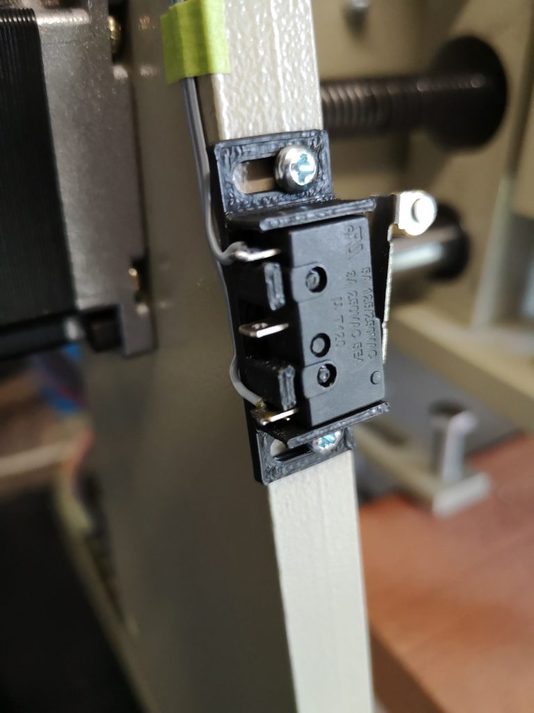
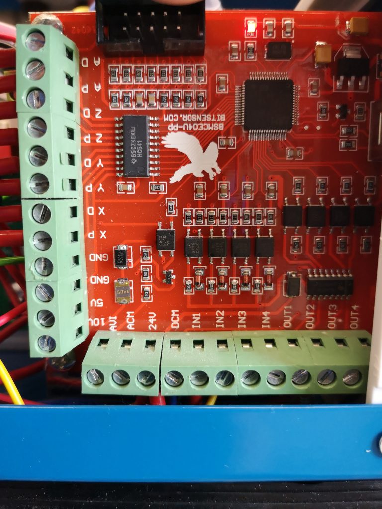
Having been used to homing the Tormach I decided that adding limit switches to the 3040 would be a good thing.   I fitted 6 microswitches and wired them in series via their normally closed contacts to create a loop.   I connected one end of the loop to the Input 2 terminal on the card terminal strip (Port 3) and the other end to ground.   Any switch when activated will now break the loop and create an alarm condition.   The same switches also perform the home reference function.  (Mach3 just looks for a break in the circuit relevant to the function being asked of it – it knows when it is homing and it knows when it is running and looking for a switch break).   

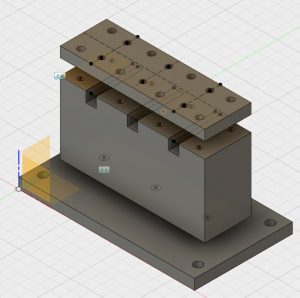
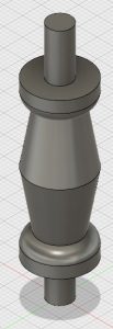
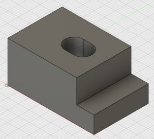
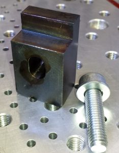
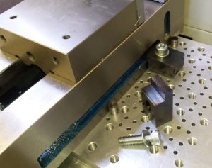
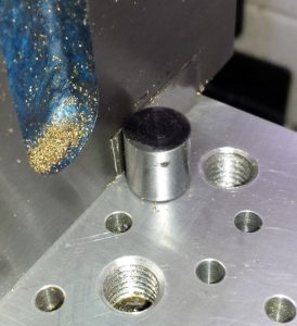
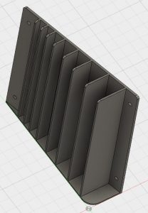
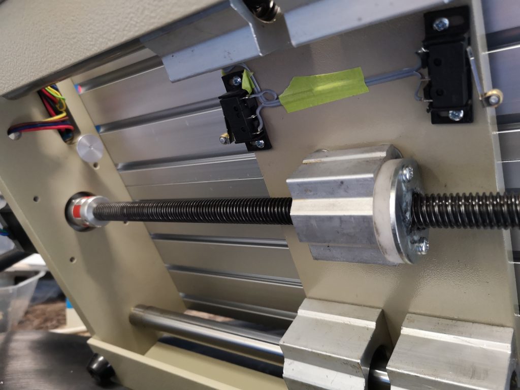
I made 3D printed mountings for the switches and covers for these.  I had to add extra wiring to the cable forms both on the machine, through the connector cable to the control box and inside the control box.   Fiddly but done. I slipped up with the +Y back stop switch in that I mounted it on the cross plate without realising that the interface cabling to the umbilical connector fouls the movement.   There was a protruding M3 screw holding the interface connector in place which was acting as a crude carriage stop.  I turned an eccentric ‘top hot’ to fit on this screw to activate the microswitch.

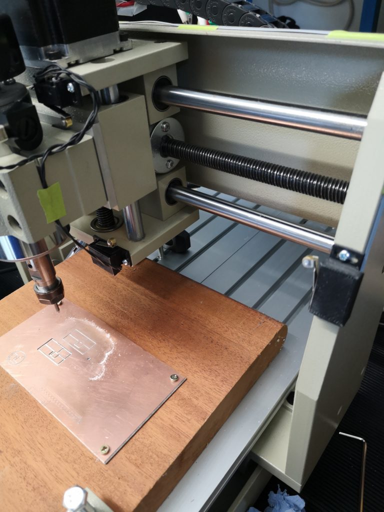
Fitting the switches has now made setting up more repeatable and it consistently goes to 0,0,0 when doing a Reference All. Having referenced the spindle head, it can then be moved to the WCS zero ready to run a job. So far I have played with the demo Mach3 which has limited lines of GCode capacity but I have run some of my small PCB milling routines successfully. So all looking good but as ever I wasn’t satisfied and wanted to make life easier by using the Tormach ShuttleXpress controller.   This involved downloading a plug in file to add to Mach3. It sort of works but it isn’t like it is on the Tormach so I am still trying to get to grips with it.

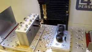
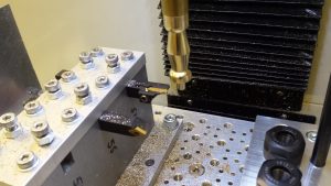
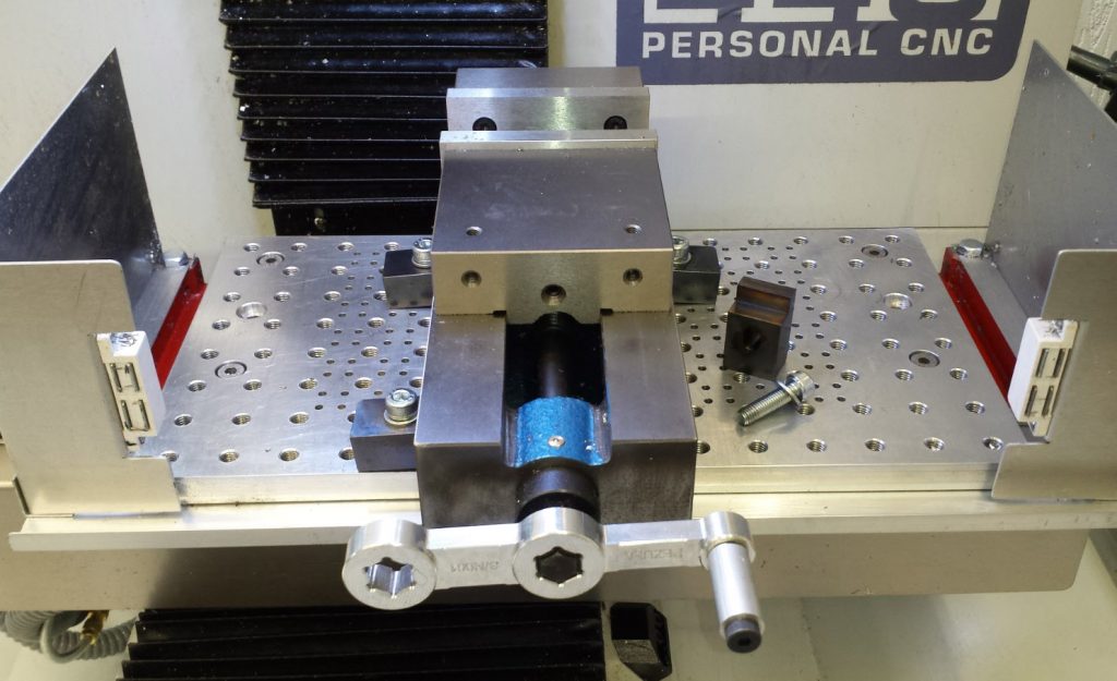
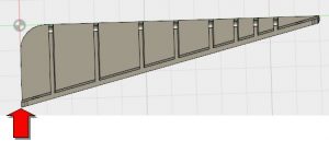
I am waiting for a delivery of TackPack superglue to stick the cable wiring in place, hence the fluorescent green masking tape.   The flat cable is standard ribbon cable stripped down to be the right number of cores as needed. Note that I replaced the backing plate on the Z mounting (the bright aluminium as seen in the first picture) as this protruded too far down and would not allow the microswitch to be easily mounted. A few pictures of progress below and more updates to follow.

3040T limit switches
View showing Z switches and one X switch with its printed cover in place
Limit switch with cover removed
Underside view showing Y limit switches and also ‘Top Hat’ stop fitted on connector mounting screw (aluminium disc in this view)
RnR USB interface card. IN1 is the emergency stop switch and IN2 is the series wired normally closed loop via the limit switches with the return going to GND

Similar or related subjects : –

A CNCEST router / engraver joins the workshop

You have probably gathered by now that I like to experience new challenges in the workshop.  I spotted a CNCEST 3040T for sale on EBay with no bids offered and on the last day of the auction.   I did some checking and discovered that these devices are quite common and are a good way to get into CNC.   There is a wealth of YouTube postings about the machines and whole libraries that you can delve into to find models to make.   I must state that it is not a Tormach type machine but more of an engraver/router device with nothing like the grunt of the Tormach or indeed other milling centres.

The one I had spotted had a USB interface and was intended to be controlled by Mach3 which is a totally different animal to PathPilot.  PathPilot is a dedicated controller for the Tormach range of devices and because of this there are lots of facilities that you take for granted but which are hidden ‘under the hood’. Mach3 on the other hand is a generic controller that can be configured to control all manner of CNC devices but because of that it is quite complex to get to grips with, particularly for someone starting out on CNC.   Some of the user interfaces leave a bit to be desired which doesn’t help but I am getting there.   Mach3 has been around a long time and has a large user base.

Back to the story.

The purchase included the control box with the USB interface, a set of ER11 collets and a fourth axis stepper motor with a chuck already installed.   It is nicely built in that it is quite substantial but is basic and my purchase did not come with a great deal of documentation. The USB interface is by BitSensor RnR and apart from the stepper motor control lines has four auxiliary 4 input and 4 output lines that can be configured for external control.

The weekend was spent YouTubing trying to get up to speed and from this I gleaned the following : – Mach3 allows you to download a demo version which is fully functional but has a restricted maximum number of lines for running a program.   No problem with this and nice to be able to play before committing to a licence.

Having loaded Mach3 onto my desktop (Win 7, 64bit) I could not get the program to talk to the mill.   This was solved by the discovery that you need to add a plug-in for the RnR USB interface card.   This allowed the spindle to be moved in XYZ fashion from the PC keyboard direction keys and Page Up/Page Down. Next problem was that the spindle movements did not seem to reflect the Mach3 DRO readout distances.   This was solved on the Settings tab using the Set Steps per Unit button.   This was rather nice in that you tell the machine how far you want the spindle to move (in XY or Z) and then you are asked how far did it actually move as measured and it then crunches in the program what the scaling factor needs to be.  Rather neat facility. I now have the basics of accurate controlled movement. 

I can run the initial lines of one of my earlier discussion FlatCam PCB milling programs and it looks as it should.   I can see this machine becoming a dedicated PCB and general engraving device that is offline to the Tormach. So where to now ?   

I want to replace the tool table with a dedicated tooling plate similar to the one I made for the Tormach.   The table as fitted is aluminium extrusion with the equivalent of T slots.  I also want to add limit switches to make it more user friendly.   This means working out how to enable the above mentioned auxiliary lines.   Some sort of height zero probe will be needed also. So a few things to think about over winter.   More notes on progress to follow. Similar or related subjects : –

Mill Turning Jig

After a few distractions the Mill Turning Jigs are complete and I have run a test piece that is representative of a clock pillar.

Mill Turning Jigs

The jigs were both designed in Fusion 360.   One consists of a large block with space for three 10mm cross section carbide insert tools and a second block with drill and boring related tools.   I have fitted three ER16 collet chucks to this to allow flexibility of tooling choice.  Both have mountings to fit onto my 25mm hole matrix tooling plate on the Tormach.

The jig manufacture was relatively straightforward with the exception of needing a new 10mm end mill having extended length (35mm) to bottom out the ER16 collet mounting holes.   I got this from APT and the edges were lethally sharp.

Design in Fusion 360
Mill Turning Lathe Tool Holding Block

Fusion 360 design
Mill Turning Drill and Boring Jig

Trial Clock Pillar

The pillar had simple geometry as below.

Simple Clock Pillar Trial Cut

I opted to base this on  the largest pillar I had come across in any design which was formed on a 5/8″ brass rod.   I held the stock in the spindle in a 16mm ER32 collet held in a TTS holder.

I struggled a bit with the CAM for the trial as the tool geometry of the tools  I recently received from Banggood were not in the standard tool library.   I got some of the settings wrong.  That aside the result of the first run is quite pleasing.

My feeds and speeds were a bit coarse and I cringed once or twice at the tortured sound of brass under pressure.   I didn’t complete the parting off as I didn’t fancy ducking from a large piece of brass spinning lose at 5000 RPM.

Mill Turning Setup showing both Jigs in place

Zoomed view of Trial Cuts

As ever there was quite a bit of learning while making both the jigs and running the trial pillar test piece.

Drop me an email if you want more information !

Similar or related subjects : –

You say Vise and I say Vice but we agree that Clamps are Clamps

When I put together the package of items that I would be ordering with the Tormach PCNC440 I probably made a mistake.   I wanted a machine vice (vise if you over the Atlantic) and the recommended size for the 440 was a 4″.  However a jaw set was not available with this size the same as it was with the 5″.   After checking with Tormach I ordered the 5″ in the belief that it would be usable.

The 5″ is serious lump of metal  and really only fits on the 440 table long ways on.  The jaw set is really nice however.   Sad to say that none of it has been used so far and if I am honest it is unlikely to be used.   A large and heavy white elephant sits in the corner of the workshop.  It is going to cost more to freight it back to swap out than is economic.   Offers gratefully received !

What to do ?   Looking around I found that Arc Eurotrade offer a range of machine vices.   In particular I liked the look of the SG Iron Milling Vices as they have flexible jaw positions and had a ‘pull down’ action of the jaws on closing.  They do not offer soft jaws but at a pinch these could be made as and when needed.   I ordered a 100mm (4″) version and it is a nice piece of kit, seems solid, but not as heavy as the 5″ Tormach.

The vice did not come with any useful fixing clamps so what to do ?  I had already made a tooling plate for the 440 table that has M8 holes on a 25mm matrix.   The plate also has additional 4mm tooling pin holes within the XY limits of the spindle movement.   The vice sits nicely between the M8 mounting holes and just needed some simple ‘L’ clamps to hold it down.

Designing and making the Clamps

I designed something suitable on Fusion and did a 3D print of a prototype on the Sindoh 3DWOX to do a trial fit.   This seemed to work fine so production of four metal ones was now needed.

Fusion 360 drawing of the clamping block

A debate now ensued.  Options at this point were : –

Use the Fusion model to CNC/CAM repeat produce four individual clamps which would need three set ups to face and cut.

Use Fusion to extend the model to have four clamps in one piece of stock to be cut to length as needed but machined using a full CNC program of all four on one piece of stock.  Each clamp would still need facing after cutting

Use the single clamp already drawn in Fusion and use WCS increments to hop along the stock and create four separate clamps for cutting off as needed.  Still would need facing after cutting.

Finally given their simplicity there was the option to run them on the Myford manual mill ….

Outcome

Well my hand goes up to say I funked it and made all four on the manual mill.   I cut four pieces of stock (24mm x 19mm) to 40mm on the Kennedy hacksaw and faced the ends to length on the Myford mill.  I jigged the Y position while sitting on parallels in the machine vice before cutting the clamping step on each.  Next came an 8mm hole central in the slot before mill extending it out 2mm either side.  Job done.

Would it have been faster on CNC ?  I don’t really know.   If I had drawn the ‘four in one bar’ version I think it would as there would have been only one setup apart from the facing off.   If I had done the WCS based version of a single clamp then four set ups would have been needed, one for each WCS plus the facing.   Either way both of CNC options would have increased my knowledge on CNC and I could have chalked another ‘result’ on the 440 fuselage mission tally board.

No excuses I know, but there is just something about manual milling and the intimacy of being in touch with the metal ……

The finished clamping blocks were made to suffer heat and then an oil dunking to blacken them off to make them look almost professional.

Tooling Clamp for milling table
Vise Tooling Clamp

Vise in place showing clamps and tooling pins

vice, vise, tormach pcnc440
Wide view of vise in place on 440 table. Note the NYC CNC training course handle finding a home.

So all of that was a bit of a ramble but you get the gist – CNC or manual.

Placement Tooling Pins

In closing the last thing I made was a couple of top hat tooling pins that sit in the tooling plate and align the vice position.   This ensures the vice clamps can sit symmetrically either side of the vice.  It makes for a quick set up if the vice has been off table.  Note in the picture below the small piece of shim to get the alignment correct.  (Lazy man syndrome creeping in again).

So the shop is now ready and better prepared to cut metal.   Note also the NYC CNC training course produced vice handle being pressed into service on the new vice.  Thanks to Kevin & John for that – was it nearly a year ago ???

Similar or related subjects : –

A Parallels Rack in Fusion and Sindoh with free Spagetti

Some time ago I made a rough and ready wall mounting rack for my parallels so they would sit to hand adjacent to the Myford manual milling machine.   I used double sided printed circuit board for the construction and while not elegant it worked OK …. until after I had finished it when I found two of the set lurking in a box with a half finished job.   I had not allowed for them in the construction and being OCD me, it annoyed me to have two lose ones that did not fit in the grand order of things.

An idle half day lead to a Fusion design to replace the tired old PCB disaster.  This lead to some thinking on how to design it.   I wanted a rack that sat on the tooling board with the parallels stacked on it with a slight upward angle to keep them in place.   I chose therefore to draw it slightly strangely with the ‘back’ at an angle and extruded it accordingly.   See below.


All well and good you might say.  Less messing with angles etc.

I squirted the job into the Sindoh 3D driver software and then tried to be clever and print it with the backside down on the printer bed …. or at least what I thought was the backside down.   You will no doubt spot that that this is not a simple rotation of 90 degrees but I didn’t.

The printer began producing spaghetti that was not bonding to the printer bed.  After three re-tries I took a closer look at my design and realised that the only part of the job that was in contact with the bed was the leading edge (red arrow below).  The rest was airborne at an angle all due to the way I had chosen to draw the object and rotate it.

Reset brain and reset printing so it would be now vertical.   All was good and my nice new rack sits on the tooling board.

A little bit more brain engagement next time perhaps ?

Similar or related subjects : –

Verified by ExactMetrics