Spluttering Banished to be replaced by a Banshee
It had become a standing family joke on steaming outings that my Polly V whistle left a lot to be desired. Quite often it would do nothing more than a feeble splutter. The Polly V kit supplied whistle is fitted under the running board on the left hand side of the cab. The pipe run is long and somewhat tortuous. I had insulated the pipe to reduce feed loss but this made little difference. The whistle valve also had a gentle leak and was very stiff to activate. All in all not a good setup.
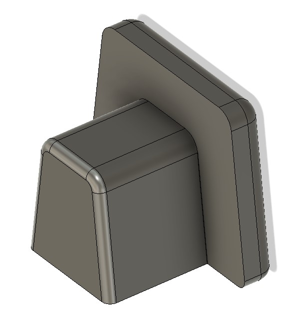
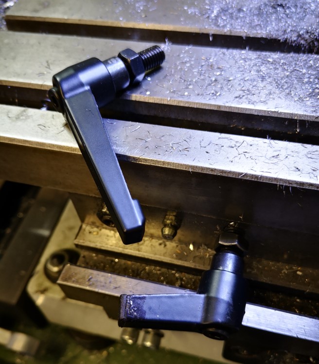
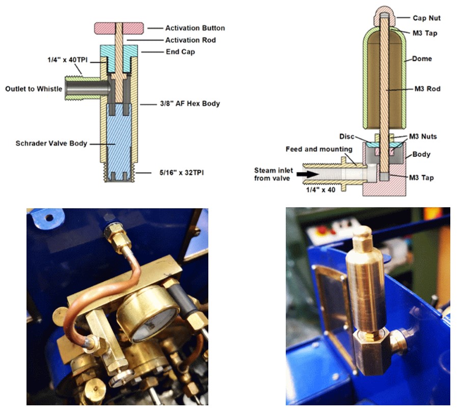
A recent article in Engineering In Miniature (EIM) by Richard Wightman (September 2022) went into detail about a whistle and valve combination he had created. The whistle was fairly conventional but very compact. The steam control valve was unusual in that he used a standard tyre Schrader valve. This tweaked my interest and I set about upgrading my Polly V locomotive using this technique. Here are some Fusion 360 images and shots of the new valve and whistle mounted in place on my Polly V.
Here is a blow by blow description of the process as a PDF download.
Links to similar or related post are listed below : –
- Model Railway Track Testing Monitor
- Swiss Vapeur Parc Festival Week
- 3D Printed Jigs to the rescue
- Rosebud Fire Grate on a Silvercrest BR Class 4
- Simple Water Level Sensor for Live Steam Locos
- French Model Steam Engine Gathering
- Replacement Whistle on Polly V Steam Engine
- Bad day steaming with my 5″ Polly V live steam locomotive
- Lempor Nozzle added to Poly V 5″ steam locomotive
- Setting up the timing on a Polly V locomotive