It was Fathers Day last Sunday and apart from spending time watching the very exciting final round of the US Open I had a visit from one of my sons and my granddaughter.
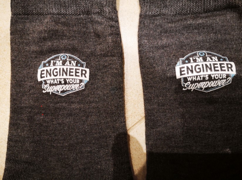
They came bearing gifts … a pair of socks. Not just a pair of socks but a very appropriate pair of socks.
It is a Superpower that we as engineers hold through our hands and our brains.
If we could just get the younger generations to understand the importance of engineering and how it creates wealth for our country and in turn contributes towards our future survival as a race.
Sheep Defences and Stainless Steel in Stainless Steel nightmare
We’ve just had 3 weeks in France and so I have been low profile in the workshop. Lots of jobs to do out there and we had 30C temperatures most days. This can be a bit draining, particularly after an extended lunch and glass or two of red.
Two main jobs done which are interesting to report on.
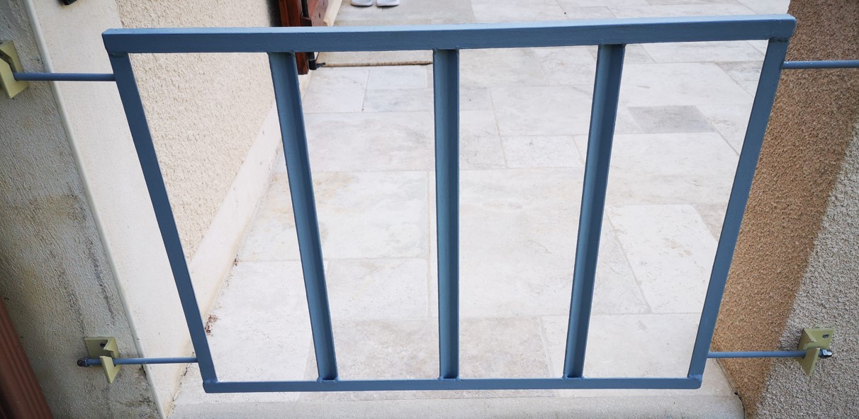
First of all we regularly get invaded by sheep who in bad weather prefer to use our terrace as a sheltering location. Sheep in France or at least our part of France do not seem to regard a fence or hedge as a barrier. If the grass is greener on the other side they are on their way. The owner of the sheep does not seem to care too deeply about this migration. Compare this to my farming upbringing in Yorkshire where we were liable for damages if our stock wandered loose onto a road and caused mayhem.
Back to the plot. The terrace has three entrances and our neighbour had helpfully taken the step of placing wooden pallets across these. This worked in stopping the wandering beasts but did not look too pretty. After the previous trip I measured up the entrance apertures and on return to the UK TIG welded some angle iron based barrier gates. These are held in place by some ‘drop in’ brackets. The TIG welding did not bare a close inspection but it created functional barriers. The mounting brackets were CNC milled on the Tormach 440. Image below.
For the first time ever I used some cold applied galvanising paint by Rust Oleum to coat the finished steelwork. This would coat easily if the metal was degreased thoroughly. I applied two coats and left it to harden. It smells and is very heady so application in fresh air is essential. Now I can’t exactly correlate this but I had a serious trouser clip session after using the stuff. Could be me. I certainly did not have a dodgy curry I can blame it on. Beware and mask up just in case.
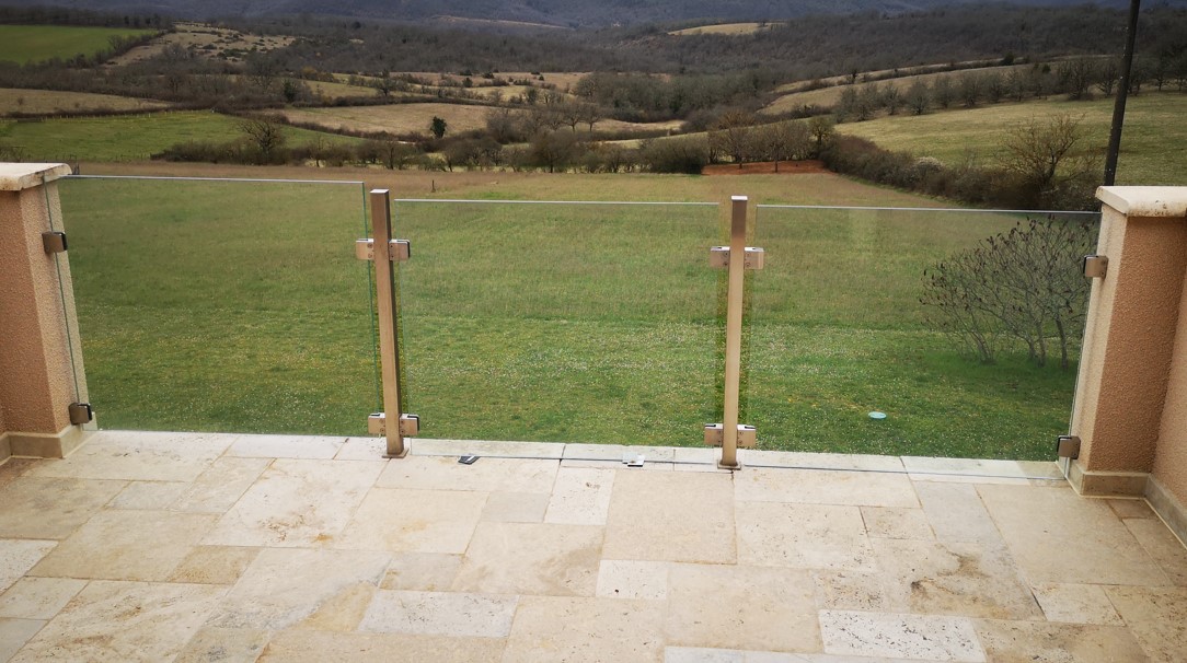
The second major problem to be solved was that we have a three panel glass balustrade on the balcony where two of the panels had slipped.
As you can see above, the glass is gripped in some stainless steel rubber padded brackets which are clamped by eight M8 stainless countersunk socket head screws per panel. Due to high temperatures two of the glass panels had slowly slipped in the brackets and come to rest on the balcony tiles. I just managed to get some expired credit cards under them.
You know what is coming next … stainless steel screws in a stainless steel body is a recipe for a bonding to take place between the two. After some serious attempts to free these screws I was left with three out of eight in one panel and one out of eight in the second panel refusing to budge. Added to the nightmare was my resulting own goal of total gouging of the hex holes in the heads of the unmoving screws.
The local Brico (aka DIY emporium) had some Cobalt twist drill at a reasonable price and a screw extractor set. I drilled down the centre of each bolt with a 5.5mm drill bit until I broke through the far end of the screw. Next step was to very carefully play a blow torch on the head of the screw (while protecting the glass) and once very hot, squirted it with freezer spray and then followed this with penetrating oil. I then left the screws to sulk for a couple of days.
Result. After hammering the screw extractor in place and applying some stiff force, the offending four remaining screws came out. It was interesting that the torque on the screw would not do anything until it reached a certain point and then click it would rotate free as if to say ‘what’s your problem’.
Having loosened the screws we than had to somehow lift the two very heavy sheets of glass. This was done with strapping tape loops at each end of the sheet and a lever rod onto the top of the adjacent post or wall. As I lever lifted, my wife shuffled larger and larger blocks of wood under the glass until we got the panels back to the correct height.
I then fitted new shorter M8 screws into the brackets with everything smothered in DC4 silicon grease. We left the panels sat on the wooden blocks and with the screws just tight enough to hold the glass vertical but not clamped hard.
The brackets as fitted are a bit like chocolate fireguards when the weight of glass is considered. I am currently looking at some additional supports that will sit under the glass (to replace our less than aesthetic wooden blocks) so the weight is supported by these and not just the original edge clamping brackets.
So not quite as restful a trip as we had planned but two problems solved.
Links to similar or related post are listed below : –
Sorry it has been a bit quiet but we had a few weeks in France and got distracted catching up on jobs there. A minor update on this will follow.
I brought back a 30 day rope driven clock to work on for a fellow engineer who lives in France. The movement has a 1 second pendulum and is marked as being made by Lawson of Bingley. I haven’t found much wrong with it other than the hands were a loose fit on their arbors and were rubbing against each other and the dial.
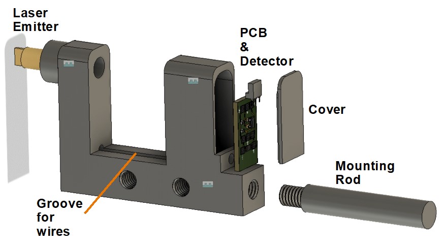
In the course of working on the clock I needed a different style pendulum sensing optical sensor to interface to my Mumford Microset Timer. This evolved before being modelled in Fusion 360 and then 3D printed. A small sensor interface PCB module was also created in Fusion Electrical and milled on my Tormach CNC mill. The body integrates the laser emitter, detector and PCB. Below is a visual image from Fusion. The pendulum swings through the U channel to break the optical beam and give pendulum timing pulses.
There are various M6 modelled mounting holes around the body. The complete unit is powered from the Microset internal 5V supply.
A complete write up is available for download on the link below.
Update : – I could not get the clock to accurate time while using a 3600 beat reference in the Microset. I did a train count and discovered that the clock is actually a 3584 beat movement. The clock is now doing very well with a few seconds per day error.
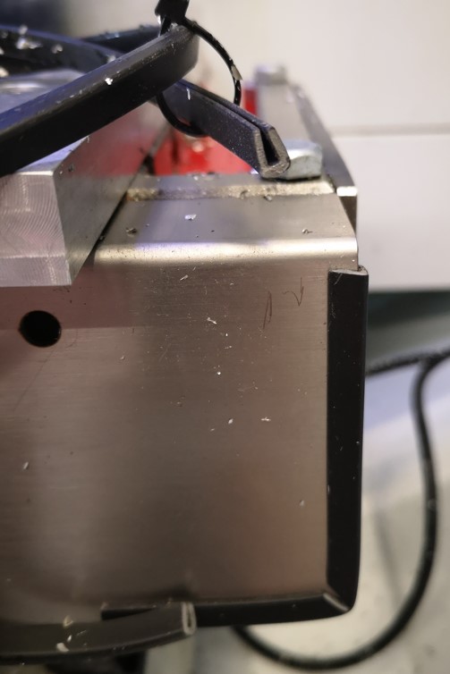
Hands up all those owners of a Tormach PCNC440 who regularly skin their hands, mostly their thumb knuckle, on the corners of the X axis stainless front skirt ?
I have tried to de-burr both corners but to no avail. It is just lethal to get anywhere near them when rummaging for a dropped part in the swarf (chips) or cleaning out the pan (do people do that or is it just me ?).
After a recent blood letting I decided enough was enough and fitted some electrical endless grommet around both corners. You have to nick out a 90 notch to allow the grommet to follow the curve but that aside job done. Hopefully less expletives in the workshop from now on but there again there will always be broken tools and Haimer tips to contend with.
Electrical grommet protecting the X axis skirt sharp corners
I have had issues when opening Fusion 360 files downloaded from third party fellow users. I never really got to the bottom of this. Sometimes they would send me an assembly file and I could open the separate items in the structure but not the overall structure itself.
Things then got worse after a visit to France when I created some straight single item models on the machine out there. On return to the UK I could not open these files getting a message “Try again when update completes”. What updates ?? Both the Fusion install in UK and France were running the same version of Fusion so what was the problem ?
I happened upon a thread in the Fusion forum that suggested uninstalling Fusion and re-loading from scratch. This solved the problem. The files all now open on all machines.
Be warned – trying to find a simple click to download button on the Fusion site without going through lots of marketing click boxes is not simple. I was expecting to just log into the Fusion site with my account details and find a hassle free download. It doesn’t seem that simple. I got there in the end though and all is running well.