Reduction in Sparkly Bits around the House
When I bought my Tormach PCNC440 in 2016 I included the enclosure kit in my order. On receipt I thought that fitting the enclosure would dominate the size of the workshop so I never got round to fitting it. It has sat in its shipping box since then. I have consequently shared quite a bit of my swarf (chips) with long suffering family.
After a recent (particularly heavy) CNC run I had a serious covering of swarf in the machine tray and because I had no enclosure round the mill, I had quite a lot distributed further afield (i.e. into the house). Domestic peace was becoming an issue. Time to do something about it.
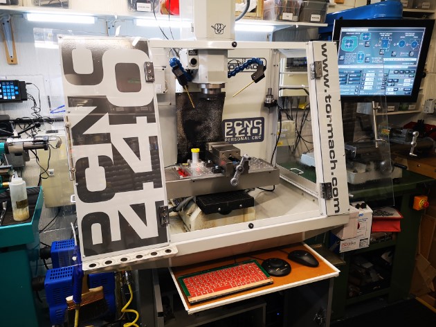
Out came the enclosure kit, cobwebs dusted off and around three hours later I had the enclosure fitted. I have to say it looks good and does not overpower the workshop as I thought it would. My wife is impressed and says it looks a more professional machine and ‘if you had it why didn’t you fit it before now’ ?
The fitting did however create some follow up problems.
My control monitor had up to now been mounted on the side of the 440 on a standard ISO TV mount. With the enclosure fitted this meant it was ’round the side’ and difficult to get to. I debated a new long reach ISO but they are expensive. Plan B was to make something. I rummaged around in my aluminium stock and with the help of Fusion 360 came up with a seriously overengineered extension arm to add to the existing ISO mount. This would allow the monitor to move forward to be in reach at the front of the mill.
This bracket became the first CNC job to run after fitting the enclosure. I am pleased to say it was the cleanest my workshop floor had ever been after running a job.
Having fitted the new bracket and mounted the monitor, all the cables needed extending. Fortunately I had had the foresight on my original order to include the extension cable kit. As a result I only had to extend the power supply lead from the monitor 12V ‘brick’ supply.
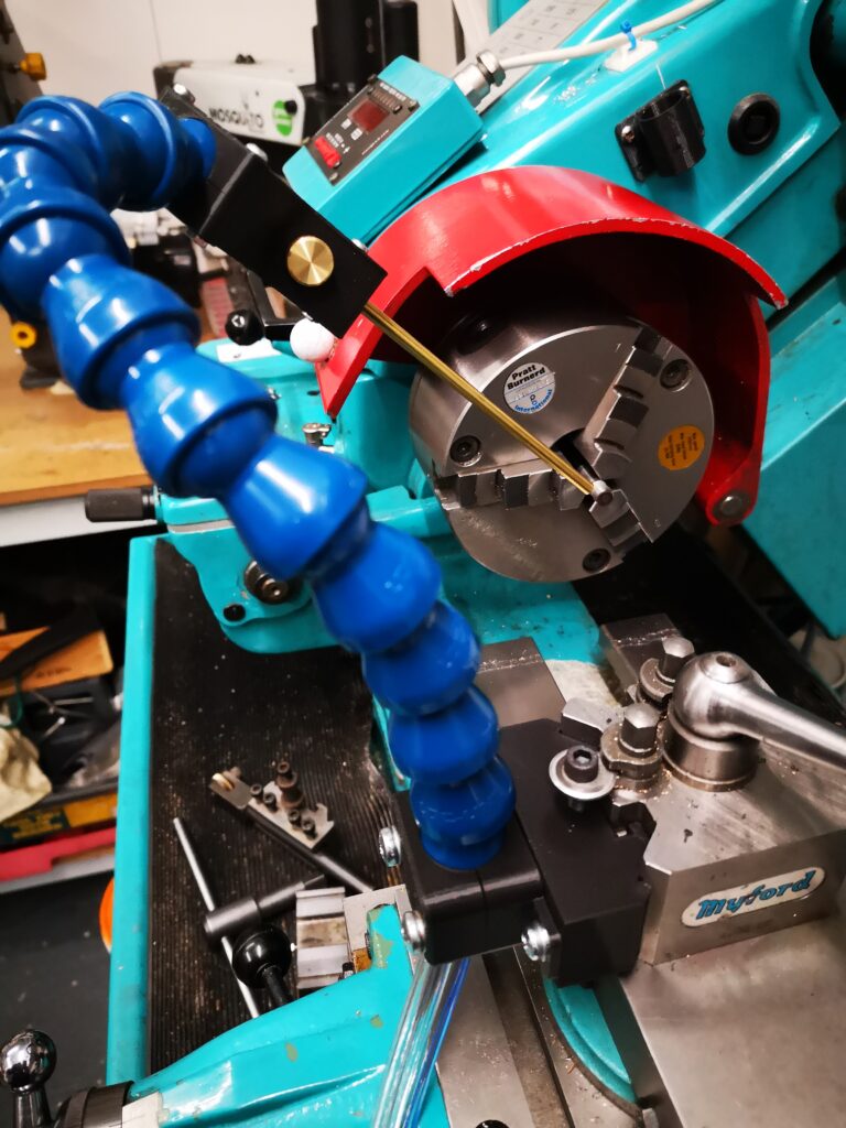
The second issue was where to mount my ITTP probe as this had formerly mounted on the side of the 440. With help of some more Fusion design I modelled a corner mount that picked up on the enclosure fastenings.

After that first heavy machining run I noticed for the first time the slight smell of the mist coolant when opening the enclosure doors. Before the enclosure was fitted the smell must have dispersed into the general workshop air. With the enclosure fitted the air was concentrated inside the mill and I only got the smell when sticking my head inside. While it had never been a problem (as far as I can tell …) I thought I should do something about it.
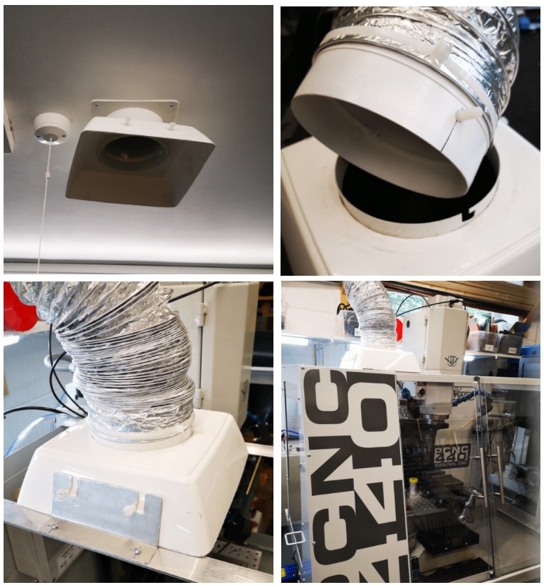
Sometime ago I installed a ceiling extract duct in the workshop. This vents to the outside world via a custom roof tile. Normally the system sits with a flared cowling (made from a cut down flower pot) on the ceiling entry duct. The system normally acts as a background trickle extract. The cunning plan in the design was to use various pipe components to provide bayonet style connection pins (Nylon screws) to allow extension trunking to be used. A bit like a BNC RF connector if this is familiar to you. This would allow me to use an add-on length of expanding flexi trunking to bring the extract nearer to any heavy fumy activity such as welding or oil bath hardening.
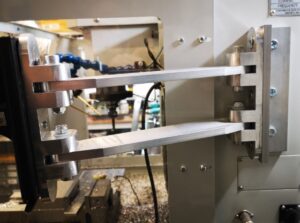
With the use of further scrap odds and ends of aluminium, I mounted a pair of support bars across the top of the new 440 enclosure. These would fix the ducting over the enclosure during heaving CNC sessions. Not a total solution but certainly one that will reduce the general smell of XtremeCut 250C when I stick my head in the enclosure.
A good day’s activity with all the issues addressed and domestic bliss hopefully restored.
Similar or related subjects : –
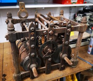
- A Very Old Burgess Bandsaw
- Notepad ++ for GCode Editing
- Local power USB switching circuit
- Tormach PCNC440 X Axis limit switch repair
- Try again after update completes Fusion 360 Error Message
- Experiences CNC machining Aluminium Composite Material (ACM)
- Engineering Video Favourites Updated List
- Burgess BK3 replacement lower blade guide
- Enclosure finally added to my Tormach PCNC440
- Update on CNC milling printed circuit boards on a homemade vacuum table