While I have been successfully using the ELS as an automatic feed, I had put off attempting screw thread cutting. You know how it is. Screw cutting is nagging at you to try, but it is on the ‘too difficult’ pile pending other more interesting jobs. There is always something else to do, so you kid yourself it is justified to put it off until another day. Well another ‘lockdown’ day dawned and I decided today was the day.
My experiences are recorded here as a full write up
This is probably not original but worth commenting on. I have a tooling plate on the bed of my Tormach PCNC440. This has a matrix of M8 holes on 25mm spacing together with intermediate 3.7mm tooling pin holes.
Quite often I have a need to set up my work CNC coordinate system (WCS) such that it is centred on one of the M8 holes.
If I want to do a quick and dirty centre on one of these holes then I use the Laser Centring tool as mentioned elsewhere on my blog.
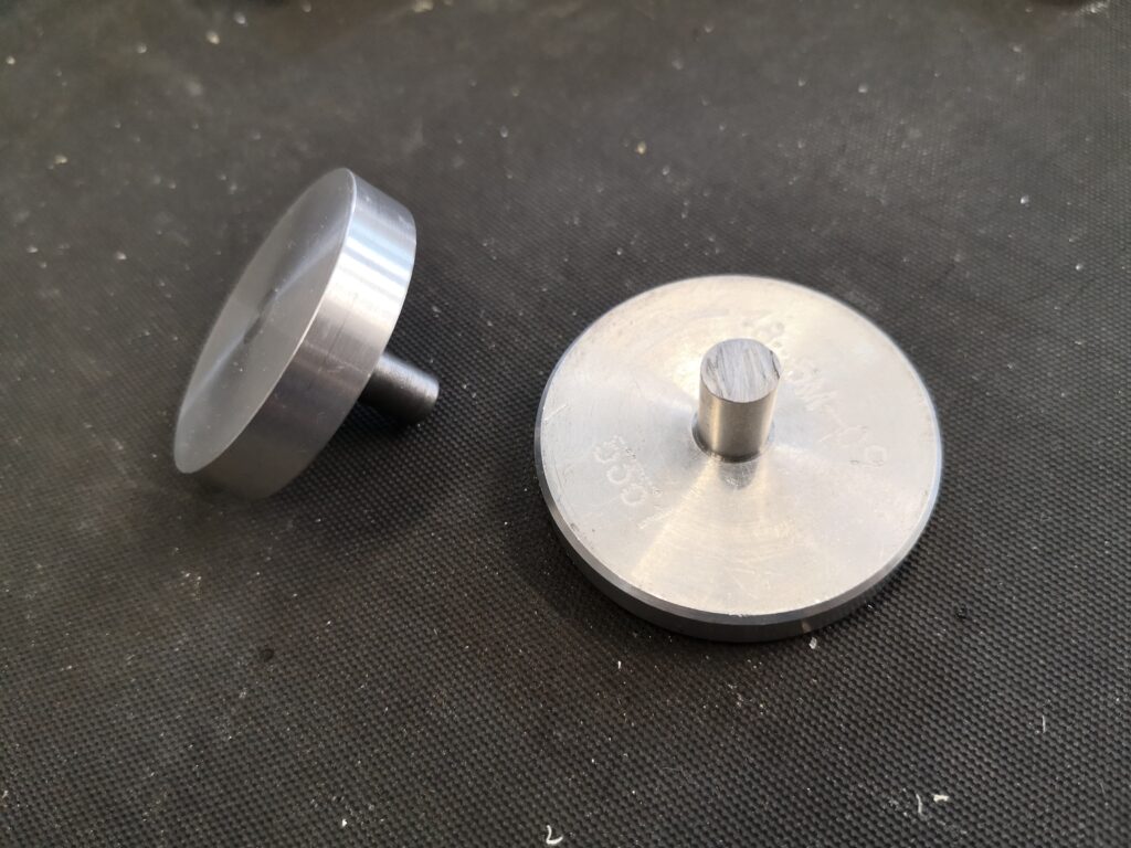
If I need to be a bit more precise then I have a mushroom/top hat shaped disc with shank that is a tight fit in the tapped M8 holes. PathPilot has a number of probing routines and these include finding the centre of a circular object. Simply push the top hat into the desired hole and then probe the disc for centre. You can use an active probe such as the Hallmark ITTP.
If you haven’t got an active probe you can use a Haimer. Simply align the Haimer tip somewhere close to a maximum point on the disc circumference and advance the axis to show a reading on the Haimer. Rock the opposite axis back and forth and watch the Haimer reading to find the high point on the circumference. Zero the axis. Go to the opposite side of the disc and repeat this process and divide the measured diameter by 2 for the disc centre. Repeat on the opposite axis.
(You can use this Haimer rocking back and forth method to find the diameter high point when cross drilling a circular item to fit grub screws etc).
Two examples from my ‘mushroom farm’
The mushrooms are made with a silver steel shank that is skimmed to be a non wobble (how technical is that ..) fit in M8 (~6.8mm) and an aluminium top hat that is superglued in place on the shank. Once the glue has set the top hat is squared up while held in a collet in the lathe. This ensures concentricity with the shank. The disc will now sit flat to the tooling table when the shank is pressed home and perpendicular in the hole.
Clearly the larger the disc diameter the less centring error there will be.
I now have a ‘mushroom farm’ of discs for all manner of hole sizes. It’s not rocket science but as you well know, I am all for a simple (aka lazy) approach. Apologies to all the Grannies out there.
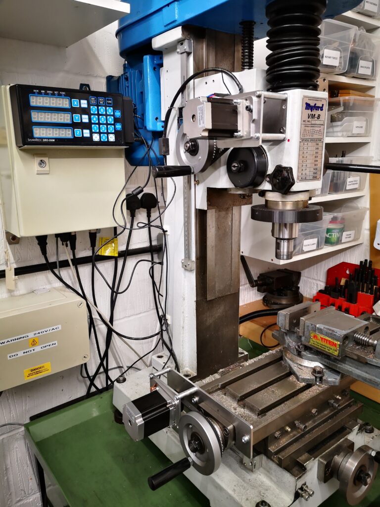
Myford VMB Manual Mill Conversion to Stepper Motor control
After many years of winding the Z axis up and down on my Myford VMB I have finally got around to fitting motor control and it is a joy to use. I am however suffering from muscle wastage as a result.
A general view of the stepper motor control conversion of a VMB manual milling machine. Only the X and Z axis are completed so far. The control box is on the wall behind the mill and has the Shumatech DRO control panel mounted on the front panel.
I have done a write up for those who might want to also enjoy a less taxing movement of X, Y or Z axis on their manual milling machine. Click on the link below to download as a pdf.
My initial tack was to create a 3D printed version. As I wanted to include the high speed option this needed a 24 tooth 5mm pitch pulley included. This did not print well.
Plan B was to buy a standard Bearing Boys 24 tooth pulley and incorporate this into the large diameter wheel. I modelled this in Fusion and concluded that perhaps a CNC aluminium part would be better. This would allow undercutting of the underside face of the pulley. This would not be possible using 3D printing as this would not be a supported area.
The stub axle that the pulley would revolve on protrudes 25.5mm from the BK3 side wall. The blade wheel groove needed to be 10.25 wide to accommodate the belt width. The retaining side walls needed to be 1.5mm wide. This totals 13.5mm width for the large pulley leaving only 12mm for the small pulley that would be needed for the highspeed set up.
This now became complicated in that the large wheel needed to sit around 5mm from the side wall to keep the belt in line with the motor drive pulley. A spacer washer was made for this. This left only 7mm width for the high speed belt and I needed at least 9.25mm just for the belt without retaining side flanges.
The light bulb moment was to realise that the high speed pulley could protrude beyond the stub axle without fouling the outer case cover. I could use the full depth of the pulley and counter bore the front face sufficiently to allow the axial retaining screw to hold the pulley assembly in place and allow free movement.
Here is a very much simplified sketch of the final assembly showing the counterbore for the retaining screw and the counterbore for the pulley boss into the large wheel. The small pulley and large wheel are locked together with 3 off radially spaced M3 x 10mm countersink head screws.
Simplified sketch of the final assembly of the large wheel on the BK3. Profiling of the wheel internal area is not shown but see Fusion image below for these aspects.
Here is a Fusion 360 graphic of the final pairing of the 24 tooth commercial pulley and the CNC machined large wheel. With hindsight the large pulley could be 3D printed by leaving the rear face completely flat rather than having a profile like the front face.
Parts needed to be bought in were obtained from Bearing Boys as follows : –
14-5M-25 (14 tooth, 5mm pitch,25mm tooth width) for the motor drive pulley.
24-5m-09 (24 tooth, 5mm pitch, 9mm tooth width) for the high speed pulley.
300-5M-09 (300mm, 5mm pitch, 9mm wide) 60 tooth belt for high speed operation
525-5M-09 (525mm, 5mm pitch, 9mm wide) 105 tooth belt for low speed operation
Note that all pulley and belt parts are to the HTD standard profile.
Here is the wheel in place with the belt set to run in high speed mode.
Replacement blade drive pulley with high speed option selected using the small 24 teeth pulley driven from the 14 tooth motor drive pulley.
Note that I had one additional issue to address.
The aluminium wheel tended to not hold the blade centrally in the blade groove with the result that the teeth of the blade would rub against the wheel front flange. This did not happen in low speed mode when the blade runs on top of the drive belt. My solution was to fit a 160mm x 10mm wide elastic band in the wheel groove only when in high speed mode. The particular elastic bands are a standard size from Amazon and others. This solved the problem. There is no abrasive impact on the elastic band so life expectancy should be high and replacements are very low cost.
The above drive modifications in addition to the modified blade guide that I have detailed elsewhere, have given my BK3 not just a new lease of life but also a more accurate cutting capability. The effort has been more than rewarded and is to be recommended.
I have created a summary compendium of all the BK3 mods and additions that can be downloaded as a ZIP file on the link below.
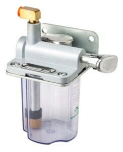
I have never been over the moon comfortable with the manual slideway oiler as supplied with my Tormach PCNC440. It has a hand pump that you pump once or twice and this fills a cylinder with oil. Inside the cylinder is a piston that empties the cylinder under pressure from a compressed spring. There are two O rings, one on the piston and one on the cylinder access end cap.
Original Tormach manual oiler
In the course of my ownership of the 440 I have had to replace the O ring on the cylinder a number of times. Once replaced the device works for a limited time and then fails again. The problem is made worse in that I can never find the right size O rings in the UK and have to resort to replacements from Tormach. These are not expensive but when added to carriage costs from the US it does become an issue.
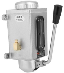
In frustration at the latest failure I found and bought in an alternative manual pump on Amazon. The action is slightly different in that pulling the pump handle action generates the pressure to feed the oil rather than leaving it to the spring return action. When the handle is released, the cylinder refills itself.
Replacement oiler which is available from a number of suppliers including Amazon
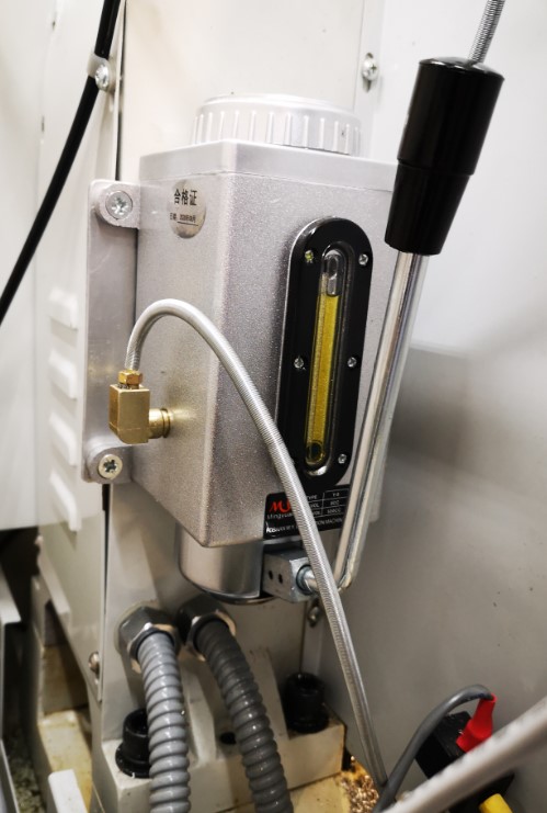
Physically the replacement device is slightly larger and I needed to make an adapter plate to fit it in the same position on the rear of the 440. The new device also has twin output feeds. This allowed me to replace the existing T splitter assembly with two separate feeds – one to the X and Y oil distribution manifold and one to the Z manifold.
Replacement oiler in place on the rear of the PCNC440
So far so good and it seems to push the oil out to all oiling points. Clearly this is something that has to be monitored or there is the danger of dry slideways and dry ball screws damaging the mill operation. I will report how the new style oiler performs longer term.
It has got me thinking that maybe using an Arduino I could create a ‘time to pump’ prompt beep at switch on and say after 4 hours of operation … a rainy day job ?


 With hindsight the large pulley could be 3D printed by leaving the rear face completely flat rather than having a profile like the front face.