Some pieces of workshop equipment generate a sentimental attraction that is hard to break. One such piece of kit is my Burgess BK3 bandsaw which is ancient but has up to now worked reasonably well for my needs. I bought it on EBay from an owner in Lancashire and remember a nice day trip to collect it.
It is a very useful machine and gets pressed into use day in and day out. That is until the other day when the blade came off with a loud twang. On inspection the drive wheel had lost part of its blade outer retaining flange. It appeared to be very old brittle plastic and the damage was really to be expected given the vintage of the device.
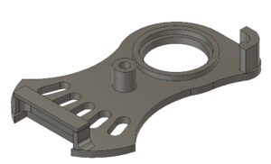
After head scratching I designed a replacement edging strip in Fusion 360 which I 3D printed and glued in place. Fingers crossed that will give the machine a reprieve and extend its life.
In the course of looking for possible spares (no chance) I came across a reference to modifications to the BK3 in Model Engineer to improve the blade tracking and speed settings. Here is a link to the articles burgessbandsaw2. I am indebted to the members of my local model engineering club who came up trumps with copies of these articles for me.
The guide modification consisted of replacing the two stud guides with ball bearings. While the machine was in pieces it seemed like a good idea to implement this modification. The Fusion 360 3D model is shown below. The blade is sandwiched between the two ball races and these can be slid in and out and then be fixed in place with the cap head screws once the correct location is found to guide the blade.
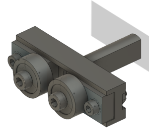
I drew the replacement guide block assembly in Fusion 360 and milled it on the Tormach CNC from brass. The 1/2″ bearings came from BearingBoys.
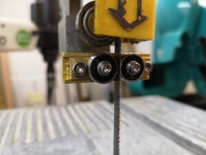
All is now re-assembled and running really smoothly. The blade prefers to run in straight lines which is a revelation.
Update : Since this blog entry I have made other modifications to my BK3 and these are contained in this link BK3 Modifications v2.
Similar or related subjects : –
- Small handheld vacuum cleaner
- Eccentric Engineering Turnado freehand turning tool
- Rotring 300 2mm clutch pencil modification
- Kindling Cracker – a safer option
- SINO SDS2MS DRO repair
- A useful Amazon sourced small item storage system
- 3D Printed Threads Modelled in Fusion 360
- Three axis stepper controller PCB in stock
- Myford Super 7 Large Bore depth stop
- Tangential Lathe Toolholder for Myford Super 7
 It is supplied with a soft storage pouch and there is a training course app with it which is straightforward. You can then play a quiz to see how good your hand / eye coordination is. Perhaps it is not good to dwell on the results of this ….
Initially it is certainly weird to use but then it seems to click (?) with brain and muscle memory and then becomes a major step forward when using Fusion 360. You use your left hand on the Spacemouse and the right hand for normal mouse activity.
I like it. In fact I like it a lot and wonder why I hadn’t latched onto it before now.
Hopefully it will ease the strain on my right wrist and probably pass the burden to my left wrist …. arthritis rules.
Similar or related subjects : –
It is supplied with a soft storage pouch and there is a training course app with it which is straightforward. You can then play a quiz to see how good your hand / eye coordination is. Perhaps it is not good to dwell on the results of this ….
Initially it is certainly weird to use but then it seems to click (?) with brain and muscle memory and then becomes a major step forward when using Fusion 360. You use your left hand on the Spacemouse and the right hand for normal mouse activity.
I like it. In fact I like it a lot and wonder why I hadn’t latched onto it before now.
Hopefully it will ease the strain on my right wrist and probably pass the burden to my left wrist …. arthritis rules.
Similar or related subjects : –