Quick and Easy Cutting Set Up
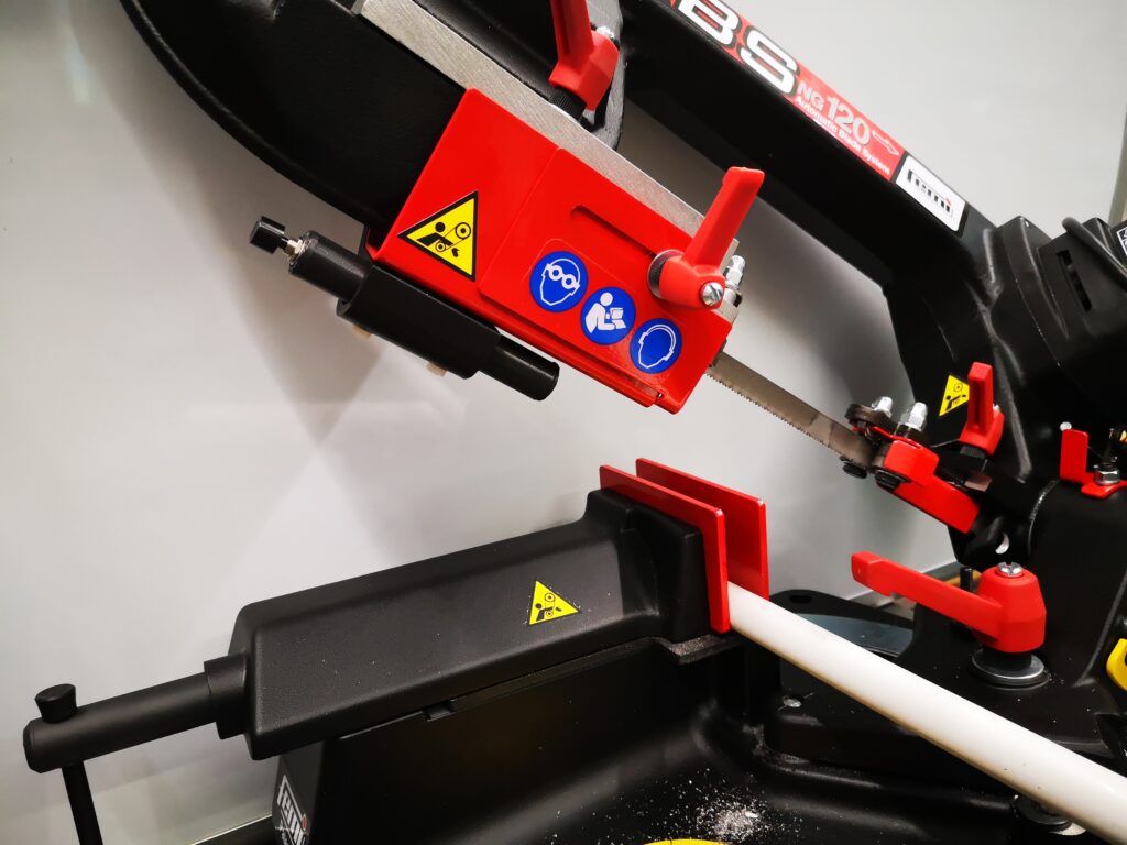
I recently acquired a Femi NG120ABS bandsaw which you might think seems a bit strange given how much I talk on this site about my Burgess BK3 bandsaw. I regard them as two different animals.
The Femi has replaced my Kennedy for cutting stock ready for milling. The Femi auto feed facility means it can be left unattended while I get on with other things.
The BK3 upgraded with my modified guide assemblies is a more precise ‘cutting to a line’ device with the benefit of a wide throat for cutting sheet stock.
I am impressed by the Femi and by its performance. Speed of cut is excellent and build quality is very good. The vice action clamps well and is very rigid.
The one frustration with the Femi has been when loading material ready for cutting. You have to iteratively and repeatedly move the stock in the vice to match where you want the blade to be cut. This is easier with long pieces of stock but when you have a heavy short chuck of metal block with not much left between the jaws it becomes a juggling act. Likewise when cutting off line such as mitres. These situations mean constantly raising and lowering the cutting arm to check you have it in the right place.
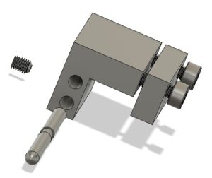
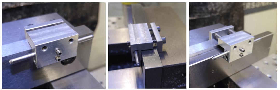
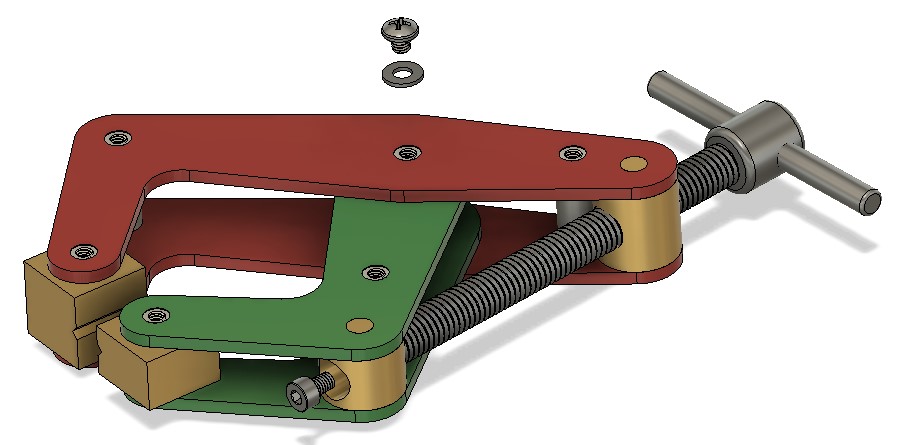
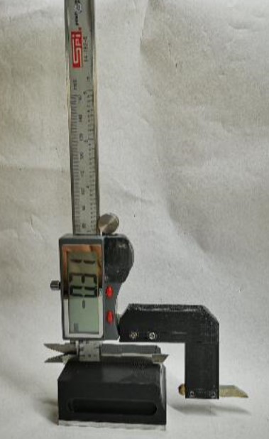
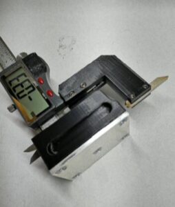
I have created a battery powered laser line module that mounts on the Femi blade guide and which will show where the blade will cut. It clearly isn’t for everyone’s taste but it makes life just a bit more simple ! As Jimmy Diresta says … ‘I’d rather have it and not need it than need it and not have it’.
Here is a pdf file containing the write up giving details.
Due to demand here are the Gerber and STEP files for the project
Because of the interest shown, if there is sufficient demand I could arrange for some PCBs to be manufactured offshore. Let me know via the email in the footer.
Similar or related subjects : –
- Small handheld vacuum cleaner
- Eccentric Engineering Turnado freehand turning tool
- Rotring 300 2mm clutch pencil modification
- Kindling Cracker – a safer option
- SINO SDS2MS DRO repair
- A useful Amazon sourced small item storage system
- 3D Printed Threads Modelled in Fusion 360
- Three axis stepper controller PCB in stock
- Myford Super 7 Large Bore depth stop
- Tangential Lathe Toolholder for Myford Super 7