Broken Tooth and No Dentist ?
The Cowells Model Engineer miniature lathe is very popular in home workshops. It is a well made machine and very accurate to use.
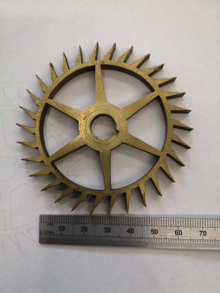
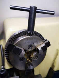
There appears to be one recurring problem with the design and that is the chuck key for the TMC3001 3 jaw chuck often ends up with broken teeth. To understand this better you need to be aware that the Cowells chuck does not have a standard style chuck key. It is more like a drill press chuck key as you will see from the image below. It also has 12 teeth which is unusual compared with drill press chuck keys which usually have 11 teeth. Using too much strength trying to over tighten the chuck rotary mechanism could lead to severe machinist depression.
I have to admit this is going to be another JSN job that slipped through the net while the sign had been left facing the wall from the last one …. a client wanted to know if I could make a replacement chuck key.
It seems that these are not readily available as replacement parts. So another little challenge was beginning to niggle at me. I thought about try to use Fusion 360 to create CAM for my Tormach PCNC440 CNC mill it but it didn’t feel like the right approach. There had to be an easier way.
While siting in the sunshine at lunch time (probably not paying attention to what my wife was telling me …. (again) …. ) I wondered if standard wheel cutting techniques could be used. This would mean a custom made fly cutter which didn’t fill me with joy and suggested a lot of grief. I then wondered if a standard clock wheel cutter might fit the same profile as the chuck key teeth.
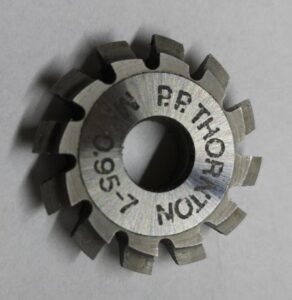
With lunch over I dug out my treasure trove of PP Thornton wheel cutters and compared them with the profile of the chuck key. The PP Thornton 0.95-7 modulus one looked a good bet as a match. In its normal life this would be a 7 tooth pinion cutter.
The idea looked like it might work. I measured and sketched up the rough dimensions of the chuck key head profile which is shown below. For ease of making a proof of concept prototype I decided to use aluminium.
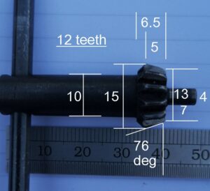
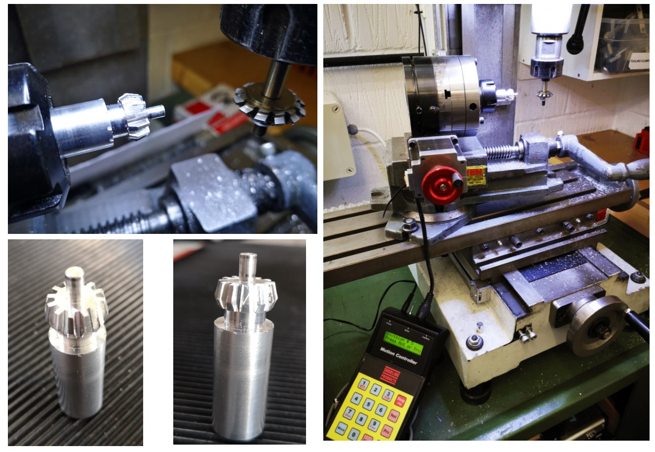
First job was to profile the aluminium stock to the outline shape of the chuck key. This completed I then mounted my Sherline CNC rotary table in the mill table vice and with some jiggery pokery managed to get the vice / table aligned at 14 degrees (90-76) to the X axis movement. I set the centre line of the pinion cutter with the centre line of the aluminium profile. I dialled in 12 steps on the Sherline and began cutting back and forth.
To match the original teeth depth I had to go down to the full depth of what the pinion cutter profile would allow. On the prototype I didn’t bother finishing the shank of the key and below are some process images and the final prototype result.
The prototype worked. I just have to make a fully finished steel version …… oh and remember to turn the JSN notice back over so I can’t miss seeing it next time an intriguing enquiry comes in.
Update : – Silver steel ruined my cutter … they are really meant for brass. Looks like it will have to be a CNC method.
Similar or related subjects : –
- Eccentric Engineering Turnado freehand turning tool
- Rotring 300 2mm clutch pencil modification
- Kindling Cracker – a safer option
- SINO SDS2MS DRO repair
- A useful Amazon sourced small item storage system
- 3D Printed Threads Modelled in Fusion 360
- Three axis stepper controller PCB in stock
- Myford Super 7 Large Bore depth stop
- Tangential Lathe Toolholder for Myford Super 7
- Hemmingway Sensitive Knurling Tool