I have my Tormach PCNC440 wired into the workshop network and as a result if a new version of PathPilot is issued my PathPilot controller warns me. This is quite nice as there is no formal emailing warnings of new issues by Tormach. Anyone whose machine is not Internet connected would need to check periodically with the Tormach site to see if an update was needed.
To continue the story … last week I got a warning of a new version of PathPilot (2.4.0) was available and I duly downloaded. One of the immediately obvious changes in the new firmware was a G37 tool measurement routine which works in conjunction with a simple Normally Closed tool setter. From my previous ramblings you will see that I had done a combiner box to allow both probing and toolsetting to share a common input to the Tormach. In theory I was therefore ready to go ….
From my many years in industry I should know that all that glitters etc … the new routine did not work. I thought it must be me but in the end I logged a support call with Tormach and sent them my log file. I also logged the problem on the NYC CNC forum to see if anyone else was having the same issue. I did get one response saying that he was not having an issue. The plot thickened and nothing back from Tormach.
A couple of days later the same responder said there was a fix update available from the Tormach site. It seems the software worked well in G20 Imperial mode but not in G21 Metric mode. He was running Imperial and I was trying to run in Metric Software update downloaded and all is well. It is rather nice. You tell PathPilot where the tool setter is located and then to run the auto tool measurement you put a G37 command in the GCode after a tool change. Away the spindle goes to the tool setter location, dunks the tool and updates the Tool Table. Magic.
Still waiting for Tormach to close off my enquiry and let me know they had fixed the problem and as a result there was a new firmware available. But it is Christmas and maybe they had other pressing matters.
I recently had a job to do where I needed to see and measure a very small part I was making. The simple microscope was struggling to cope or at least I was struggling to cope with it. Looking on the net to see what the current technology could offer I spotted a device on Amazon that looked interesting.
It was a bit more expensive but nowhere near a ‘proper’ professional optical product. Having taken delivery it is very impressive.
It can act as a simple standalone viewer using the built in screen or can be externally connected via HDMI to a monitor or (and this is the impressive bit) it can be connected to a PC via a superb application that has so many bells and whistles it will take me ages to understand all the functions. The sensor is a 16 Megapixel Sony CMOS 1/2.3″ HD device and video output can be 4K/2k/1080P. Magnification is up to x300.
So I am well pleased with the investment and it will certainly earn its keep.
Sorry that things have been quiet but we have been on a 6 week trip to New Zealand. It was the only country that my wife and I both had heard so much about and both agreed we wanted to see. So I had to bid farewell to the workshop for longer than I really wanted but you can’t go round to the other side of the world for just the weekend.
We flew Emirates from London to Dubai, Dubai to Melbourne and Melbourne to Wellington with a few hours stop over at each. If we must fly long haul we like Emirates or Virgin whenever possible and Emirates once again was brilliant.
We had considered doing a golfing holiday through a package deal but it ended up like some sort of crazy route march with tee times booked months in advance. Not really a holiday. We chose instead a camper-van do your own thing style tour. We were both a bit apprehensive about being in close confines for 6 weeks (instead of our normal me in the workshop and my wife playing golf). It took a few days to get into the swing of things and work out a routine but once we were sorted it went well.
We covered over 5,000 kms wandering around North and then South Island. We usually booked one night’s camp site ahead. We used the Top10 sites most of the time but also some independent ones. Some sites were very good, some not so good. We had one where we felt like cleaning our shoes when we came out of the toilet block …
We covered a significant part of both islands and were blown away by the scenery. We struck lucky with the weather with the sun following us around on our journey. We did get to play golf but rather than pay NZD200 for a round we played small town courses for NZD30 tops. The courses were beautifully manicured, most were deserted with an honesty box for green fees and we met some interesting people.
I didn’t get to see much mechanical tech but there were a few heritage steam railways and museums that I couldn’t resist visiting.
It is a great destination and despite my reservations, the camper-van was a great way to see things and the 6 weeks flew by. Highlight for both of us was a front seat helicopter flight from Queenstown to Milford Sound via a glacier landing and with blue skies all day. Not many people see Milford Sound in sunshine. We were very very lucky.
The workshop awaits and my newly installed heater will ensure a cosy winter activity session.
Great to be back and it will be even better when we have shaken off the jet lag.
I recently bought a special offer price tool height setter from Banggood. On arrival this seemed nicely made and robust and looked like a worthy addition to the armoury.
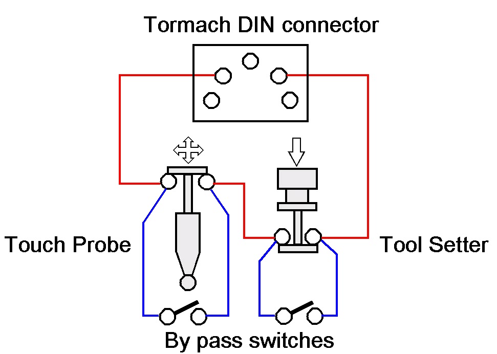
The Tormach PathPilot control software has facilities for tool height setting using such a probe. I also have a Wildhorse Innovations probing tool for edge and centre setting. Both these devices can be connected to the Tormach PCNC440 external input accessories connector which is a 5 pin 180 degree DIN.
The input to the Tormach accessory socket is a 2 wire connection. Sensing and operation of external tools like the probe and tool setter depends on the device having a normally closed connection that goes open circuit when activated (i.e. the probe tip moved or the tool setter pushed down). The probes are in essence a single pole normally closed switch.
Frustration Sets In
After spending time having to keep swapping these two devices in and out of the accessory connector I figured there must be a better way.
The Tormach does not care if you connect multiple probes at the same time provided they are all in series on an electrical loop to and from the two pins on the interface connector. Any device when activated will break the loop and create an interrupt to the PathPilot software. Because you will be in the area of PathPilot software that relates to the function you are measuring, the relevant probe will be the one you are intending to use.
The Solution
What was needed was a simple interface box that allowed the two probes to be connected in electrical series back to the two pins on the DIN connector. I also wanted flexibility to be able to unplug either of the two probes and not affect the operation of the other. This meant that on removal of either probe it would need an electrical short circuit across the pins of the connector from which the tool had been removed.
This could be done with a small by-pass switch, that is normally open circuit, connected across the connector. You would manually close this switch if the probe is removed.
This is fine so long as you remember to activate the switch when you remove the probe otherwise the sensing loop will see an open circuit and the software will get confused.
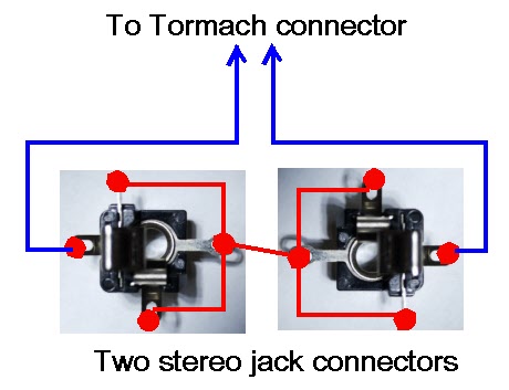
My solution was to use sockets for the connections that would automatically provide a short across their contacts when their mating plug is removed. A good example is an audio style jack plug socket. These come in various sizes (2.5mm, 3.5mm, 1/4″ etc). Usually on these sockets the tip of the connector gets shorted to another contact when there is no mating plug in place.
I had some 3.5mm stereo jack plug and sockets to hand (either mono or stereo can be used as it is only a two wire connection) and these were simple to wire for this application.
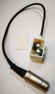
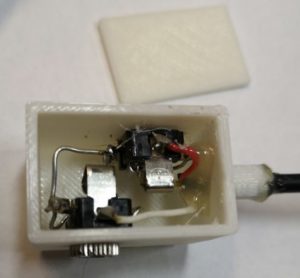
I also ran a modified version of one of my standard 3D printed enclosures to mount them in and fitted a flying lead to a 5 pin DIN to plug into the Tormach interface. A hot glued magnet onto the bottom of the enclosure allowed flexible mounting of the box somewhere on the Tormach body. The only fiddly bit was replacing the existing connectors on the two probes with a 3.5mm jack plug. (Don’t forget to the put the connector shell on the cable before you solder the wires in place ….. ).
A neat solution and the problem solved. Both devices plug into the box to perform their various probing functions into PathPilot. Unplug one of the probes and its mating socket will automatically short out the probe connections when the plug is removed. The remaining probe plugged into the other socket will continue to function.
(Note for some reason WordPress has redated this post after I did some edits ..)
We got the electric bill for last winter and there was a sharp intake of breath … maybe the fan heater had been on too much in the workshop and maybe I did forgot to switch it off once or twice when going to bed … something had to change.
I did some research on diesel heaters as used in motor homes and commercial vehicles and the concept looked like it would meet my needs. I did some calculations on the workshop volume I needed to heat as an empty shell. With my insulation and window content this came to a figure of 3kW. Searching on EBay revealed lots of kits and ready built units so my first thought was to order a ready built one. This duly arrived and I decided to run it up to see what happened.
Actually nothing really happened.
The fan came on ran for a few seconds and then the unit shut down. The controller was showing a severe droop on the supply volts even thought the PSU was rated at 10A. More web reading and comparing notes with other users revealed these units take a serious current surge at switch on while the glow plug is warming up. If it sees a voltage droop it thinks it is in a vehicle and switches off to protect the vehicle supply.
Bigger power supply acquired and plugged in. Still no joy. I then realised I needed to prime the fuel line. Quite a few clicks of the pump later I had a full pipe feeding the device and finally it ran up. The fan was flat out and the pump was clicking like a French grenouille on heat.
And what a stink it made. I guess it was burning off all the manufacturing oils but it was pretty acrid. Finally the fog cleared and I could see the neighbours house and we had heat. Quite a lot of heat. Fiddling with the pump rate brought the heat and the fan rate down and all seemed good. But it was noisy.
There now followed some serious navel contemplation. Did I really want this fire breathing Smaug inside the workshop ? Not really. So how to solve the installation ?
Immediate thought was to mount the unit external on the side wall and feed the warm air from the unit into the workshop and take in air from the outside to warm. The smelly exhaust inlet and outlet would also then be outside. Not a good idea taking outside air and warming it unless I wanted a very rust rich environment.
So air would have to circulate from the workshop, get heated and blown back inside. This means two 80mm holes in the workshop wall plus a power and controller wiring duct of say 20mm. A plan was forming and I could see where the two air ducts could be located.
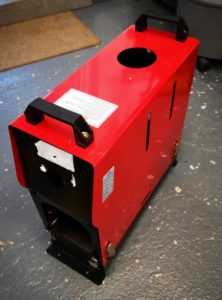
Next problem the (I have to say very horrible) enclosure my ready made heater came in would not protect the contents nor would it last very long sat in the outside air.
New Enclosure
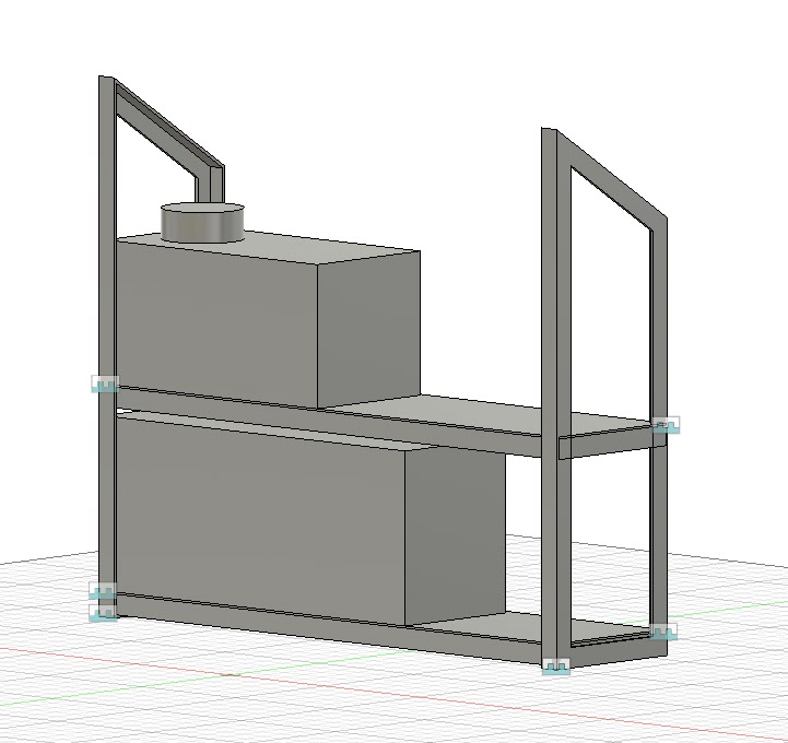
Much Fusion 360 playing later I had a design based on a 20mm angle iron frame and aluminium sheet covering.
Original Fusion 360 model of the enclosure frame less the two top bracing steels
The angle iron and sheet were ordered from Aluminium Warehouse and came very quickly. I was now going to have to grasp the nettle and refresh my TIG welding knowledge to create my first major TIG construction. (I only have TIG as MIG scares the **** out of me).
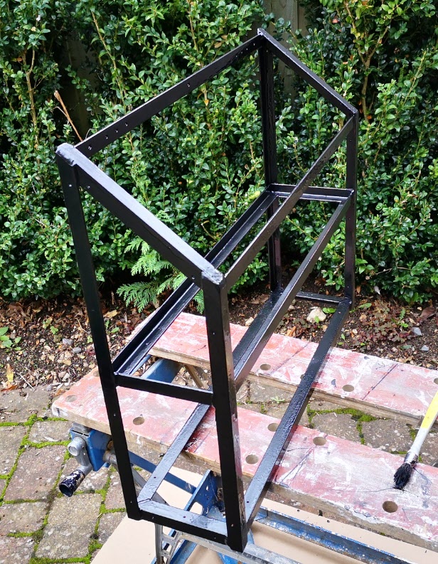
Even though I say it myself I was pretty chuffed with the frame that resulted. Some of the welds were far from ticketable but my angle grinder and Hammerite paint soon covered up my ineptitude.
TIG welded heater angle iron frame after clean up and painting
The aluminium covers also stretched my resources as I don’t have a formal metal bender but I do have some very long lengths of angle iron and a robust vice. Two side walls, a front panel and drop on top cover resulted without any serious clangs. Loving it.
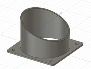
The return air inlet needed an interface of some sort so a Fusion model was created and printed (6 hour print …).
3D printed diesel heater 80mm air inlet cowl which took 6 hours to print
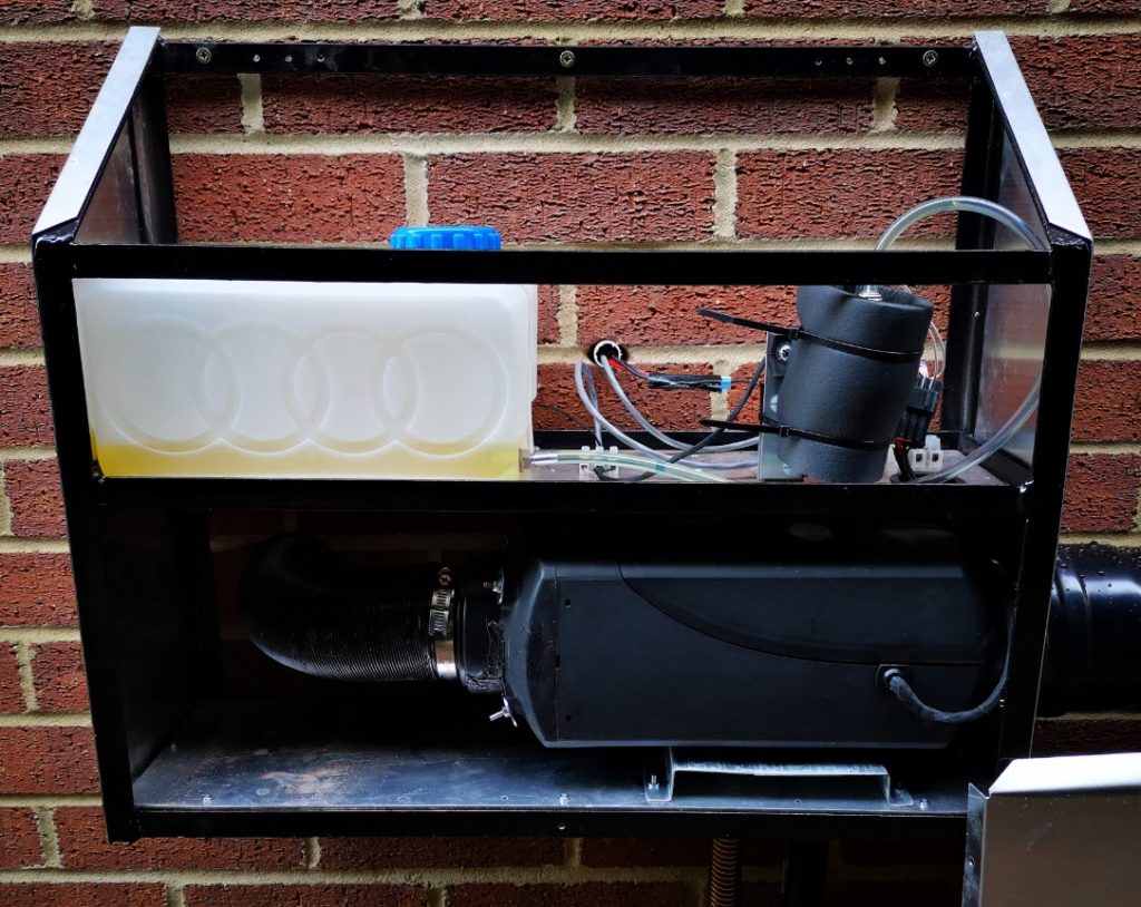
With the enclosure complete, I mounted all the components and ran it up again. The new power supply also failed to do the biz so I decided to go with a meatier version inside the workshop rather than inside the external cabinet.
Installation day loomed. I was very ably assisted by Dave who is a long time friend. We are both cut from the same engineering mould and we usually end up with an interactive plan of action.
First job was to cut the hot air duct hole in the workshop wall. We had a long pilot drill, an EBay 80mm cutter and a SDS drill. Serious grief. The workshop outside brickwork seemed to have a Titanium content. We finally broke through into the cavity and thereafter the inner Thermalite block was like cutting chocolate cake in comparison. First hole finished and more to the point in the correct position.
We now offered the unit to the wall to match the routing of the hot air outlet pipe of the heater. We put a car jack under the unit to keep it in position while we drilled the mounting holes. Holes drilled, we then mounted it on the wall and drilled the cable duct and lined it with a piece of uPVC water pipe.
Re-boxed diesel heater enclosure mounted on the workshop outside wall. The pumps is enclosed in some foam to deaden the clicks.
The circulating return air from the workshop was to come through the workshop wall and back to the heater from just over a meter away. I had a suitable length of 80mm spiral metal ducting for the air return and a mating right angle joint to route this through the wall. We marked off the duct hole position and drilled out a second 80mm hole (more grief, less dust as we damped it down, and hammer and chisel when we got fed up with the useless 80mm cutter).
The Cunning Plan
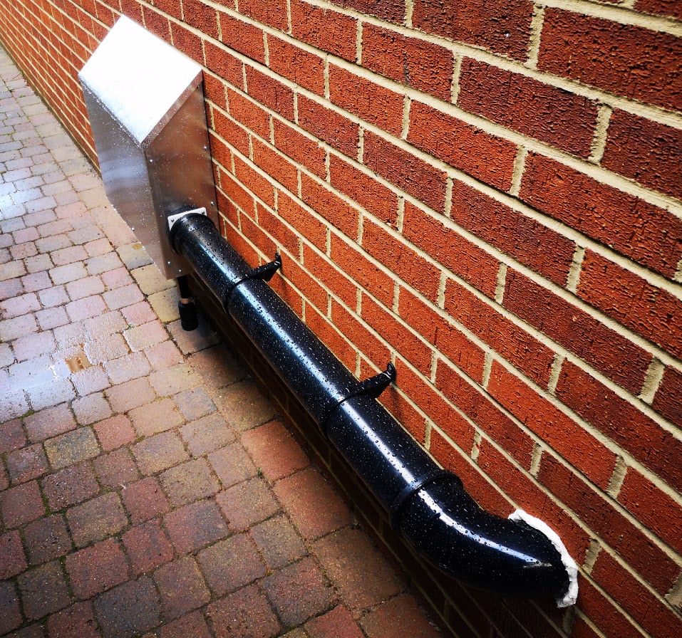
I didn’t want the metal spiral ducting exposed to the elements and also saw it as a source of heat loss. There is no point in heating up the workshop and then send the warmer air outside to lose heat on its way back to the heater. The solution was to buy a standard 1m length of 110mm soil pipe and a right angle joint with two mounting clips from Wickes. We wrapped the 80mm spiral duct in bubble wrap (quite a few turns) to fill the space inside the 110mm soil pipe to make a coaxial structure. As luck would have it the spacing to the wall of the soil pipe was pretty much ideal to use the standard pipe clips. We did however have to cut down the right angle soil pipe connector to get it flush to the wall. It then got a dose of squirty foam to seal it.
Finished diesel heater enclosure with coaxial inlet duct using 110mm soil pipework and fittings. The 80mm internal duct is wrapped in bubble wrap.
We were both very pleased with the result. As Dave commented it looked better than a professional install would have done.
This was the bulk of outside work done apart from mounting the exhaust inlet and outlet pipes. Inside we had the hot in wall vent grill to fix and the controller wiring.
I still haven’t decided where to route the outward air duct but currently it sits sucking air from under the Myford Super 7 cabinet. I am not comfortable with this (the location rather than the potential draft around my ankles) as it will tend to suck up workshop dust and particles. Some form of filter will be needed. As yet I haven’t mounted the new power supply on the inside wall.
We ran it up and I can describe it as toasty warm. At least one good reason to look forward to winter, probably the only one.
Finally thanks to Dave for helping. Also thanks to Steve Niebel for detailing his experiences with a similar unit.
If you want to know more about the heaters then the best source I found on YouTube was Dave McK 47
Anyone wanting a very basic indoor housing for their heater components should send me a message ….. and soon …. otherwise it is going in a skip (but I might save the handles).
Update December 2021
The heater has now been installed and running for over 2 years. It is excellent in making the workshop more than comfortable in winter months. A few comments to address feedback I have had on this post : –
The controller cable was extended into the workshop by simply cutting the supplied cable and splicing in an extension length of 3 core cable.
I now run a mix of diesel and household heating oil (approx 50/50) which does not seem to degrade performance. That being said the brickwork near the exhaust is now somewhat black from the fumes. I don’t get any smell in the workshop with the pipework routing as described.
Fuel consumption is around 5 litres per week if I run it every day for four hours.
I fitted a simple mesh filter over the air intake which remains located under the Myford stand.
With hindsight there is more than enough hot air generated that I could have branched the feed to my office next to the workshop.
Overall this was probably one of my best projects for the knock on benefit.