Solution from frustrated experiences
Not something of general interest – our house in France has an Odealis LPG fired boiler. This provides both hot water and central heating and works very well and is good on efficiency. The hot water side is particularly good in that it is on demand when you run a hot tap and has a limited buffer volume of hot water stored internally.
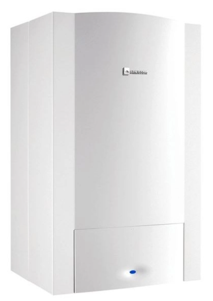
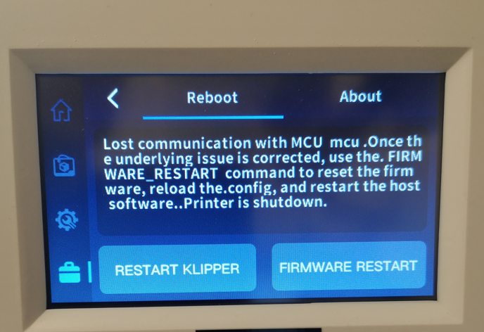
For sometime we were having problems which resulted in an A9 error message being shown on the control panel. We had a service engineer call twice on this issue and no real resolution. The symptoms were that on demand for hot water the boiler would fire up, run for a short while and then the over temperature cut out would kick in and the boiler stop firing until it had cooled down sufficiently.
If you look in the handbook for error code A9, it tells you to check the temperature measuring thermocouple. This checked out okay and was not the issue.
The boiler has a device called a plate heat exchanger (French term). It is a laminated stack of copper capillaries that have both the hot water and the central heating water flowing independently through them but thermally coupled. It is a heavy lump of metal.
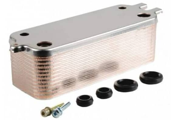
My thinking was along the lines of if this gets blocked the flow reduces through the capillaries and the water temperature rises as it cannot be easily conducted away. I couldn’t decide which side could be causing the problem. We do have a water softener installed which would tend to suggest that the problem was not on the hot water side but more likely on the central heating section.
I requested a service call and this time told the supplier unequivically that I wanted the heat exchanger replaced and that he should leave the old unit in the utility room for me to inspect on our next visit.
On arrival the over temperature problem had gone away. On inspection the old heat exchanger was clogged with metal debris liberated from the inside of the radiators. The capillaries are so fine that this was always likely to become an issue with age and usage.
Having replaced the heat exchanger, I decided to try to alleviate future problems by fitting a Vortex magnetic trap in the boiler return feed. This is a large Neodymium magnet in a trap that forces all the return water to circulate around it and grabs the metalic debris. The trap can be valve isolated so the magnet can be periodically removed and cleaned.
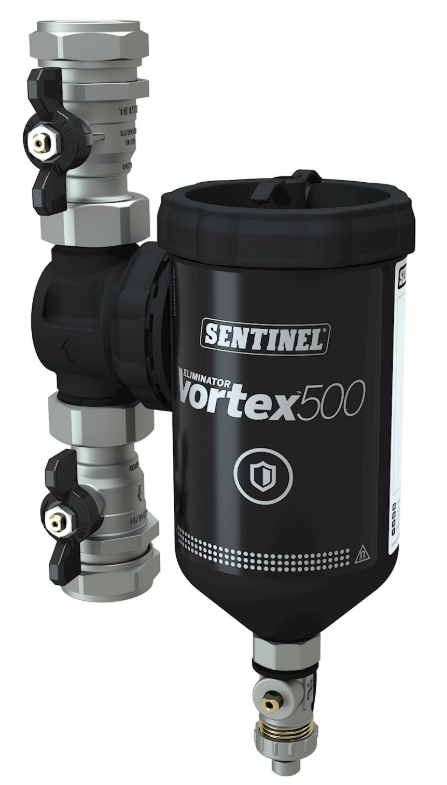
Hopefully the problem has gone away and the new exchanger is better protected from blockage with the magnetic trap doing its job.
Sorry not very interesting but just might save someone the same frustration we had with a supplier who didn’t really understand the source of the problem.
Links to similar or related post are listed below : –
- A poor man’s ring gauge set
- Error Code A9 on Odealis Gas Boiler
- Power banks that go to sleep with low current drain
- GyroCut versatile scalpel replacement
- Dry lining wall fastener fixing aid
- Simple Vice tommy bar modification
- Soldering Iron bit storage on Lytool soldering station
- Water Softener goes AWOL
- Ubiquitous Dishwasher Tablets and their uses
- One Hundred Subscribers