What on earth is this weird creation ? ……..
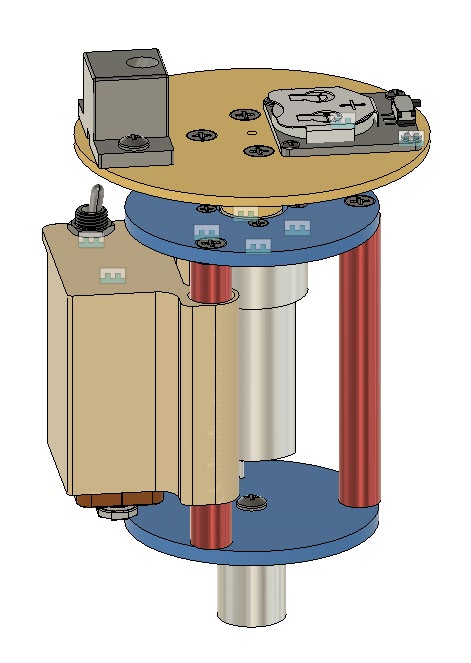
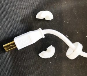
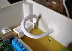
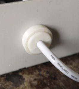
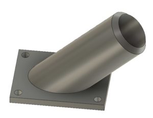
One of my favourite additions to the workshop has been a laser centring tool for use on my Tormach PCNC milling machine. The tool consists of a low cost laser diode mounted on a 3D printed disc and with a 19mm steel shaft. The tool is held in the Tormach spindle power drawbar. The laser is angled inwards towards the spindle axis at approximately 20 degrees. The 3D print has facilities for a battery supply and ON/OFF switch such that when the laser disc is pulled into the power tool bar collet it switches on the diode.
In use, as the spindle is raised or lowered, the rotating diode creates a circle of light on the milling table which can be used to locate and centre the spindle on features of the item being machined. This might be to locate the centre of a hole or the centre of a block depending on need.
A full write up of the mill related item is available here.
I recently had the need to use my four jaw centring chuck on my Myford lathe. Usually I duck and dive to avoid having to use the 4 jaw as I find it frustrating to set up. This recent bout of frustration lead me to wonder if I could adapt my laser centring tool for use on the lathe such that it would give me a guide ring of light to show where the material was sitting relative to chuck centre.
On the milling version the laser rotates and the job stays fixed. On a lathe version this would be similar. The chuck would be stationary and the laser would rotate in the tailstock.
The full write up can be downloaded here. and the Fusion 360 file is here lathe_centring_device v4
Similar or related subjects : –
- Small handheld vacuum cleaner
- Eccentric Engineering Turnado freehand turning tool
- Rotring 300 2mm clutch pencil modification
- Kindling Cracker – a safer option
- SINO SDS2MS DRO repair
- A useful Amazon sourced small item storage system
- 3D Printed Threads Modelled in Fusion 360
- Three axis stepper controller PCB in stock
- Myford Super 7 Large Bore depth stop
- Tangential Lathe Toolholder for Myford Super 7
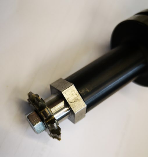
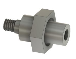 It is made from a piece of 19mm AF hexagonal steel bar with the hexagonal flats going to be used as a tightening it in place in the Tormach arbor. My Myford Super 7 when used with a 3 jaw self centering chuck is not bad on concentricity but for really accurate centering I swap the chuck for a collet face plate instead. This job was going to need both.