I bought three Kafer dial gauges in an EBay job lot with a view to making a dual gauge holder as per Clough42’s design.
After some thought I realised that a single holder would suffice by just flipping the orientation of the dial gauge in the holder. Rather than machining the holder I opted to 3D print as this would be sufficiently robust when gripped in the QCTP of the Myford.
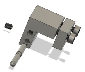
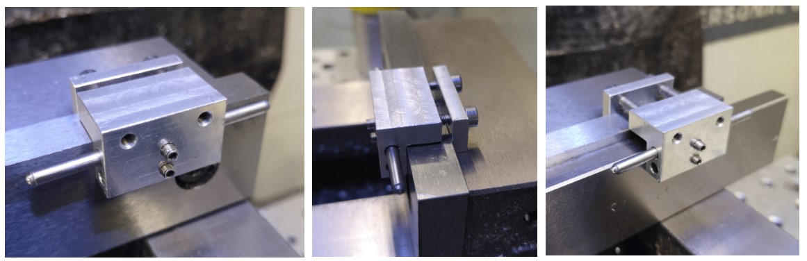
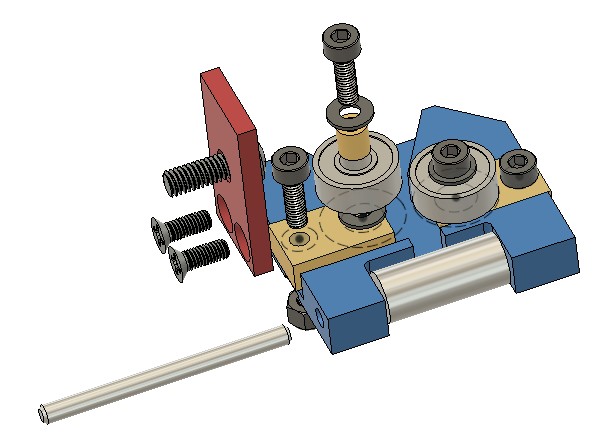
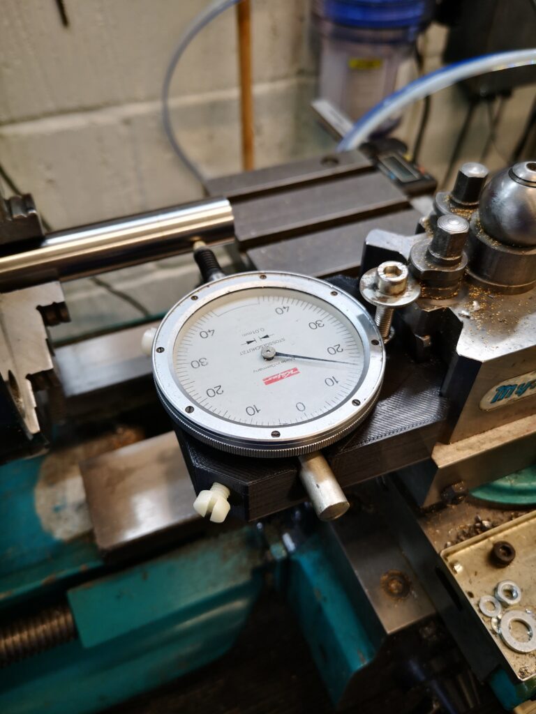
Here is the Fusion image and a picture of the finished holder in place. The gauge is gripped in place by two nylon screws. A M5 cap head screw acts as the height adjuster in the QCTP.
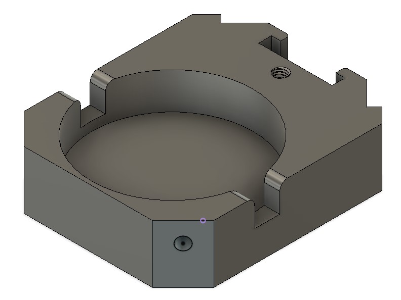
The threaded holes are all M5 and 3D modelled in the print. They just need a run through with a tap to clean then up.
The following link has a ZIP file containing the Fusion file and STEP file along with the dimensioning sketch for the QCTP geometry.
Single dial gauge mount ZIP file
Similar or related subjects : –
- Fanttik super tool is well worth a look
- Small handheld vacuum cleaner
- Eccentric Engineering Turnado freehand turning tool
- Rotring 300 2mm clutch pencil modification
- Kindling Cracker – a safer option
- SINO SDS2MS DRO repair
- A useful Amazon sourced small item storage system
- 3D Printed Threads Modelled in Fusion 360
- Three axis stepper controller PCB in stock
- Myford Super 7 Large Bore depth stop