Sorry it has been a bit quiet but we had a few weeks in France and got distracted catching up on jobs there. A minor update on this will follow.
I brought back a 30 day rope driven clock to work on for a fellow engineer who lives in France. The movement has a 1 second pendulum and is marked as being made by Lawson of Bingley. I haven’t found much wrong with it other than the hands were a loose fit on their arbors and were rubbing against each other and the dial.
In the course of working on the clock I needed a different style pendulum sensing optical sensor to interface to my Mumford Microset Timer. This evolved before being modelled in Fusion 360 and then 3D printed. A small sensor interface PCB module was also created in Fusion Electrical and milled on my Tormach CNC mill. The body integrates the laser emitter, detector and PCB. Below is a visual image from Fusion. The pendulum swings through the U channel to break the optical beam and give pendulum timing pulses.
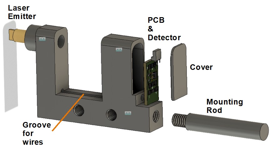
There are various M6 modelled mounting holes around the body. The complete unit is powered from the Microset internal 5V supply.
A complete write up is available for download on the link below.
Interface to Microset Timer v4
Update : – I could not get the clock to accurate time while using a 3600 beat reference in the Microset. I did a train count and discovered that the clock is actually a 3584 beat movement. The clock is now doing very well with a few seconds per day error.
Similar or related subjects : –
- Arduino Processor Reference Clock Accuracy
- 3D Printed Length Gauge for In Barrel Mainsprings
- The “Modern Clock” by Goodrich
- Microset Timer interface using Fusion 360 3D model with Fusion Electrical
- Clock adjuster rod for measuring spring and fusee drive power
- Update notes on modifications to the Devon Sea Clock
- A church clock problem and lockdown timekeeping
- Repairs to an ancient Thwaites clock completed
- Further 3D printed soft jaws for the Thwaites clock escape wheel
- Vice soft jaws and then soft soft vice jaws