I had been using Hall Effect devices to modify my William Smith Gearless Gravity Arm clock and had been surprised by their ease of use and repeatable trip points. (More about this to follow in a separate post).
I had also been frustrated with my inability to set tool heights reliably in PathPilot despite using various methods all of which didn’t want to agree with each other.
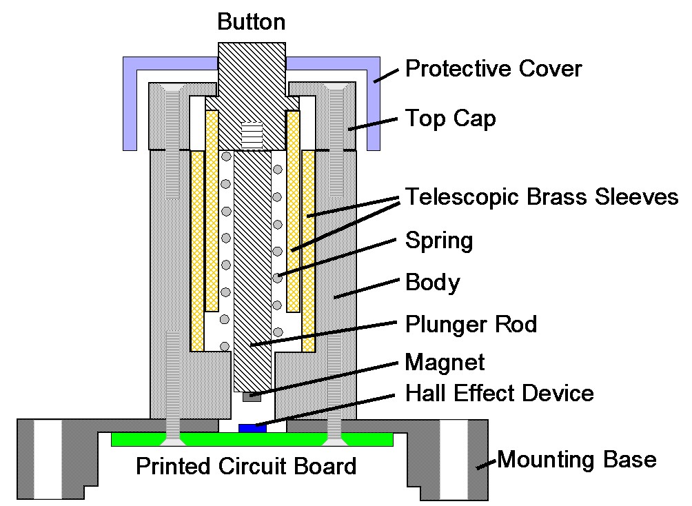
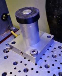
This resulted in the construction of a Hall Effect based Tool Height Setter that appears to solve the problem. The write up is lengthy so I have committed it to PDF for download but here are a couple of images to give you an idea of the result.
A simple cross section sketch of the tool height setter concept using a Hall Effect sensor
Finished tool height sensor mounted on the PCNC440 milling table
Lots of activity to be documented and posted but let’s start off with a short note. Not earth shattering but might help someone somewhere.
I had the bright idea of using Micro USBs as a connecting medium on a couple of projects. This was driven by the need for a 5 wire connection. The design was finished and I dug out the Micro USB to Micro USB cable that had been bought in for the project and connected things together. All the LEDs went out on my project circuit board. Gloom.
After buzzing the cable through I found that on a standard Micro USB cable the Sense pin is linked to the Ground pin. There are not 5 independent and isolated cores as you would expect. Just four. What to do ?
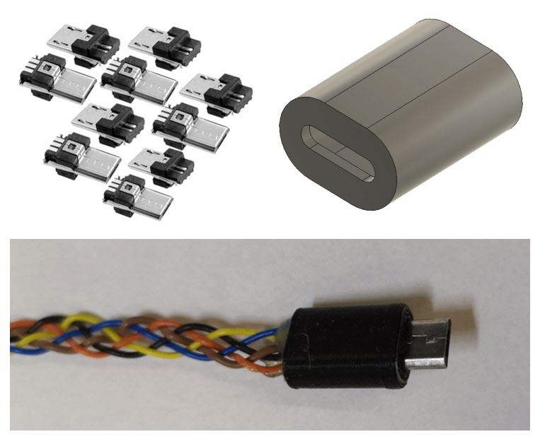
By chance I had some Micro USB connector ends with solder tabs but no shells. I did not have any flexible small diameter cable with 5 cores. After some discussions with my other half she offered to plait 5 independent cables together for me as a cable form. These were soldered to the Micro USB ends. Two small end caps were quickly designed in Fusion 360 and took 10 minutes to print on the 3D printer. Job complete and project back up and running.
Custom Micro USB 5 core cable components showing solder terminal end connectors, 3D printed shell and plaited 5 core cable courtesy of my wife.
While I have been quiet for the last month or so there has been some intensive work by Dave and myself on FlatCAM. We are in the throes of doing a formal document to help others get to grips with the process and techniques for milling circuit boards.
I need to also put my hand up and admit going over to yet another dark side by experimenting with Arduino technology. This came about as a follow on to the work on silencing my Bill Smith Gravity Arm Gearless Clock. With the help of another colleague we have replaced the discrete timer logic board with an Arduino. I have learned quite a bit in the process and more details will follow.
Finally like many others round the world, myself and my wife are socially distancing ourselves at the moment but every cloud has a silver lining and this does mean I am spending even more time in the workshop doing ‘stuff’. It has also been a good time to look at the workshop and make plans to tidy, organise and structure things better. Some of the accumulated odds and ends are getting sifted and sorted and binned as appropriate.
Previously on Woody’s Workshop … I had spent time trying to get a consistently level PCB blank clamped to the tooling table ready to mill the traces using CNC. The results were not too bad but being anally fussy it left a bit to be desired, particularly if the board had a large area which magnified the variations.
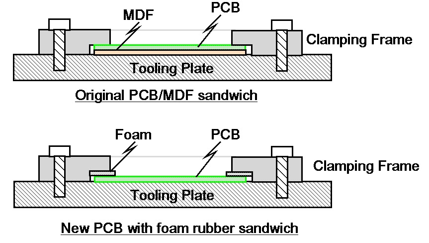
Any variation of the level of the PCB top surface will produce variable width cuts when using a V shaped cutter. I had machined a clamping plate which was a simple open frame with a clamping step equal to the PCB thickness (1.6mm) and a sheet of MDF or hardboard as a sacrificial backing board.
Despite having more clamping screw holes than a magazine burst from an AK47 I still ended with the corners of the PCB being a few thou lower. Results were shall we say ‘variable’. I had reason to run a new prototype board this week and once again hit the same frustration. In the end it was a sit and look at it and have a think session.
The resulting revelation was maybe the sharp edges on the step are applying too much pressure ? What if I were to be more gentle with the clamping ?
I cut some strips of thin foam rubber and put this into the step such as to push down on the PCB. As a quick test I only fastened the frame down using the four corner holes.
Sketches showing the two methods of clamping the printed circuit board ready for CNC milling
Absolute magic. The PCB surface hardly moved the Hamer needle at any point on the surface. Milling result was an artwork to be proud of.
Issues – the current step on the clamping frame is meant to clamp to a hard stop based on the sum of the PCB thickness and the sacrificial material thickness. Adding the foam meant I had to do away with the sacrificial board. The frame step therefore needs to be deeper. The sacrificial material is essential to allow drilling to take place without breaking the drill as it runs into and potentially damages the tooling table. (For the board in question I drilled to only 1mm and then over drilled by hand off line to the mill).
So a worthwhile bit of experimenting and hopefully a better result going forward
You will find details of my activity building the Bill Smith Hip Toggle Gearless Gravity Arm clock elsewhere on my site. This was the first clock I ever made and it taught me a lot about techniques all of which were well documented by Bill in his write up and in his many other books and videos.
Let me state now that the clock design as intended by Bill works and works well. It has one distinct disadvantage that every minute or so it gives a very loud ‘clunk’ as the pendulum amplitude diminishes, the hip toggle triggers and the solenoid resets. Running it in the workshop was fine as I became immune to the noise but sadly the clock will never progress into the house given my wife’s sensitivity to noise.
This has been a frustration to me as the clock looks splendid and its motion work action is a fascination to behold. It deserves to be on display in a more public arena than the workshop.
All of which lead to some head scratching and a compromise re-design. If I accept that the clock is an electro-mechanical device then my conscience allows me to consider other electro-mechanical solutions that are significantly less noisy. This is the fundamental premise to my re-design.
There are many clock designs that use magnetism attraction and repulsion as the driving force and my thoughts turned to this as a potential solution.
I 3D printed a magnet holder to fit on the pendulum rod. This holds two magnets. There is a large one facing the direction of swing and a small one perpendicular to the swing towards the backboard. I mounted a Hall Effect Sensor (HES) on a prototype board onto the back board at the mid swing position. The gist of my idea was to have the pendulum swinging back and forth across the HES with the HES being triggered by the small magnet. I would count the number of swings detected by the HES and after a defined number of swings I would energize a solenoid to repel the large magnet.
There was a little bit of electronics involved. I had a 4060 binary counter counting the swings and used the divide by 32 output to trigger a 555 in monostable mode. This would create a delay period from the mid point to the end of swing before the solenoid was energized. A second 555 would then define how long the solenoid repelling pulse would last. I also added LED indicators to all key timing points so I can easy diagnose what was going on. I also allowed selection of the 16,32 and 64 divisions from the 4060 until I established the optimum choice.
The pendulum period is 4800 beats per minute so one swing lasts for 750ms. The first 555 must therefore provide a delay of 375ms before energizing the solenoid. The second 555 delay would be a ‘suck it and see’ period to be determined.
The concept was lashed up and worked OK …. except that the pendulum amplitude just grew and grew until the large pendulum magnet attached itself to the solenoid core …. not a good idea . What was needed was a maximum amplitude detector to act as feedback to inhibit the solenoid pulse action.
A second HES was mounted at a position that represented the maximum swing position and the output from this, when triggered, would feed back to the 4060 RESET pin to stop the count until the amplitude diminished sufficiently. This worked and the result was very repeatable. There was one proviso that the pendulum must be started by triggering the over swing HES and releasing. Without this the 4060 could be one count out of step and would energize the solenoid as the pendulum was swinging back from its furthest point. This would cause a repelling and slowing of the swing.
Overview image of the new pendulum sustaining mechanism. Top left is the timing board and lower right is the Hall Effect Sensor board. The solenoid is the original Bill Smith design. The white block on the pendulum is the magnets holder. You can see the two Hall Effect Sensors hanging below the blue prototyping board.A close up view of the Hall Effect Sensor board where the two sensors can be more clearly seen along with diagnostic LEDs and interface converters to the timing board. The pendulum magnet holder can just be seen coming into shot.Oscilloscope display showing the yellow regular negative going pulse from the centre swing HES detector, the blue delay pulse to allow the pendulum to travel to its extreme and commence its swing back and the purple pulse triggered from the back edge of the delay pulse which defines the solenoid ‘On’ time.
The prototype has proved the concept but I now need to engineer a clean solution. First choice is perhaps an Arduino Mini but it could also be PIC based.