A convenient way to make a cuppa
This one is a bit of a curved ball story and won’t appeal to all readers …. but is worth recording.
In the 1970s my business was in its infancy. I was working from home trying to get things moving. One lunchtime we had a knock on the door and on answering it I was met with an individual saying “Hi I’m Derek and I am your Farnell Electronic Components rep and I’m taking you out to lunch”. So began a working and personal relationship with Derek Palmer and FEC that lasted many years.
Derek eventually resigned from FEC and began trading as Turnkey Manufacturing Ltd, a one man company specialising in sourcing electronic components, assemblies and services from the Far East. As a Company we continued to use Derek to source items for us.
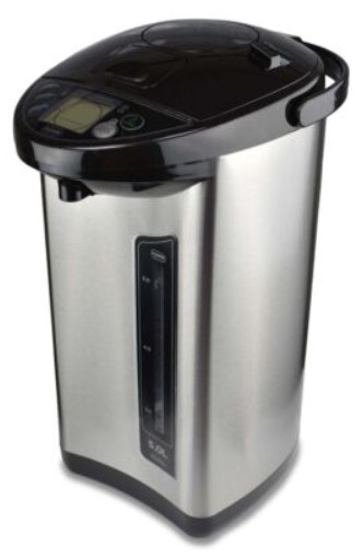
In the course of his travels in the Far East Derek came across the Thermopot concept. This was a stored hot water boiler that gave ‘close to boiling water’ on tap for making hot drinks. Derek grasped the potential for such an item in the UK market. He began working with the overseas manufacturer to adopt the idea to meet the EU market standards. Very soon he and his wife Jan had a growing business selling the Turnkey version of the Thermopot.
The Thermopot was not perfect. It came in two versions, either a 3.5L or a 5L capacity. In theory it kept the water at a constant temperature of 98C but this was not always stable. The water tank had a sealed lid which stopped the water from de-oxygenating. It had dual heating elements, one for initial boiling and one for maintaining the temperature. An electronic controller managed all the functions.
Needless to say Derek persuaded us to buy one. Our initial cynicism abated and our kettle was soon relegated to the back of a cupboard.
The story now takes a sad turn. One morning in 2014 Derek woke up and went downstairs to make a drink where he collapsed and died. We regarded Derek as an honorary member of our Company such was the relationship he had with us. Everyone was shocked by the loss. I am sure the same feelings were expressed up and down the country in many other small companies that had come to know him.
Jan, Derek’s wife, sold the rights to the Thermopot to Addis who market a wide range of household wares. Over the course of time we have had one or two replacement Thermopots from Addis. It would be inappropriate to comment on their level of customer support other than to say that it is not on a par with how Derek believed customers should be looked after.
Last week our current Thermopot went AWOL. Out came the kettle to keep the cups of tea flowing. Rather than waiting for Addis to respond we decided to just buy a new one. We discovered two things. First of all it is cheaper to buy one on EBay direct from Addis rather than Amazon. Secondly the pictures on EBay of the front panel suggested that there was an updated version now being offered. This was confirmed when the delivery arrived. I have to report that so far the new version keeps the water temperature at a very stable 98C and our cups of tea are much the better for this. The pump that streams the water also has a higher water flow rate.
Being of an engineering mind I stripped down the broken one. It was quite basic on the electrical side. What surprised me was that there was no insulation material around the hot water vessel. This would have greatly improved its energy efficiency. Judging by the temperature of the case on the new delivery, there is unlikely to be insulation in the new model either. Perhaps something for Addis to consider in the next iteration ?
Sorry that wasn’t of much interest but at least Derek Palmer is now enshrined in internet lore. He was a lovely guy, keen sportsman and full of fun. He is very sadly missed by all who encountered him. Whenever we make a cup of tea we think of him.
Links to similar or related post are listed below : –