Wildhorse Innovations Passive Probe

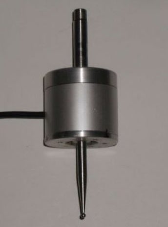
I bought one of the Wildhorse Innovations Passive Probes some time ago and it gets used occasionally (usually when I have dispatched another Haimer tip to happier hunting grounds).

wildhorse innovations passive probe
The Passive Probe as supplied by Wildhorse Innovations

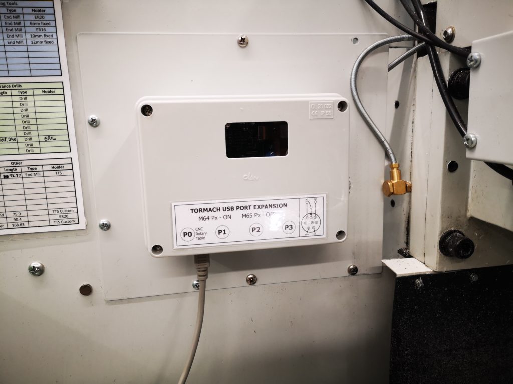
The Wildhorse design is nice and simple and it can be bought with a ‘Tormach Option’ which is a cable with a ready fitted 5 pin DIN that is pre-wired to plug straight into the Tormach 440 accessories socket.   I have to say it did not talk to the Tormach PathPilot interface immediately.  I had to snipped the pull up resistor inside the unit to solve this.  When in use on the Tormach you have to designate the probe as Tool 99 in the tool table so as to be able to utilise the PathPilot probing routines (which are very good).

So where is all this going ?  Well it is a A to B to C progression …

I dusted the probe off to use the other day and as I had not used it for some time, I did a centring calibration of the probe ball point while mounted  in the Tormach spindle.   This is a real pain to do as the three centralising adjustment screws are on the bottom face of the body.  As a result you can’t see what you are doing and there is a danger of knocking your dial gauge in the process and having to start again.

This got me thinking about whether I could do this adjustment off line in the lathe.  This way the adjustment screws on the bottom face are readily accessible.   This seemed like a good idea except the umbilical cable is permanently wired into the unit so it needed to be protected from a disastrous wrap round the chuck.  Initially I wrapped the cable around the body of the probe and held it there with masking tape but it wasn’t ideal.

Watching the probe spin in the lathe chuck made me also realise that because I had mounted the probe in a Tormach TTS collet this was a waste of a collet. It might also be adding to eccentricity through using such a combination. So you see that one thing leads to another and to another.   A workshop wormhole.

A plan was made.  Fit a connector on the probe body to allow the cable to be disconnected and replace the existing mounting rod with a TTS equivalent.

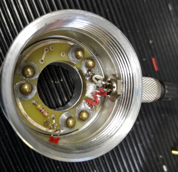
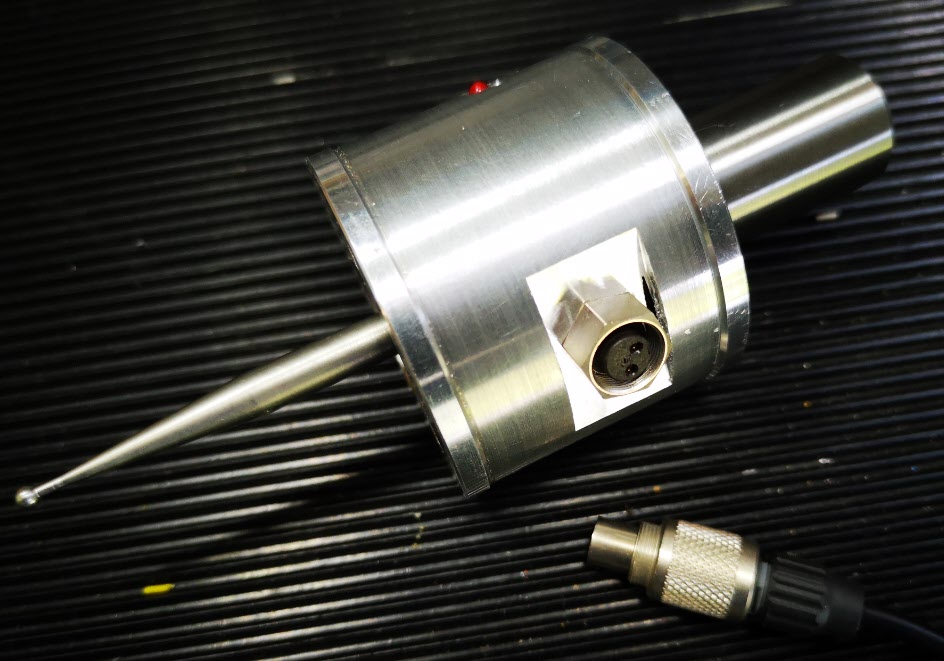
Finding a suitable connector was a bit more tricky than expected in that there is not a lot of room inside the probe body and a connector that protruded too far would foul the spring loaded mechanics.   My search for a suitable connector combination Iead me to a 2 pin Binder rear mounted socket (Part Number 09 0074 00 02).  Being pedantic it should be a fixed plug as the connecting cable connector (Part Number 99-0071-100-02) would now have two exposed pins carrying a voltage.   The supplier only had the fixed socket version in stock so I conveniently looked the other way on that argument – the cable would rarely be unplugged so not likely to be a problem …

The circular body of the Wildhorse Probe is quite substantial.  When the connector arrived and I was ready to proceed, I took a picture of the existing wiring and then snipped the cable clear.  I enlarged the hole in the body wall to 9mm but then discovered that the mounting thread on the connector was not long enough protrude through the probe body wall far enough to pick up on the retaining nut.   To overcome this I milled a flat area on the shell outer surface.  The two connecting wires where then soldered in place on the fixed connector and then on the mating male connector on the free end of the cable.

wildhorse innovations passive probe internal view
Internal view of the probe after the Binder socket had been fitted

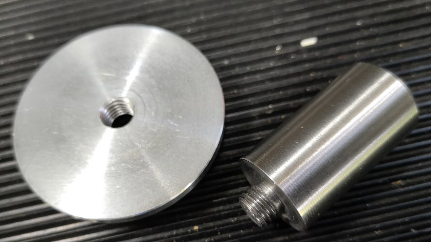
The next job was to make the new fixing rod.   I always try to have 19mm silver steel available in my stock box.  This matches the TTS collet outside diameter.  I decided I would make a new mounting rod with the silver steel and I would increase the threaded mounting hole on the probe top to M8 from the 1/4″ size as supplied .

wildhorse innovations probe top with new M8 mounting
Top cover of the probe inside view of the M8 inside the spring retaining counterbore

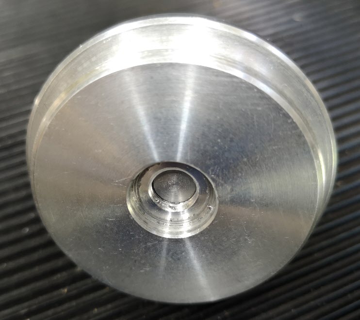
The larger diameter would provide a larger shoulder on the rod to tighten against the probe top. Using M8  would allow the stud mounting hole to still sit within the pocket that retains the pressure spring.   The rod was faced and turned to 8mm for 5mm or so and the M8 thread cut and undercut with a graver.   The other end of the rod was faced and then a 45 degree chamfer turned on it. The finished rod screwed nicely into the top plate and the body now seemed to run solidly square to the central axis.

Wildhorse innovations probe new mounting rod and body top cover
The new 19mm OD silver steel mounting rod and the outside surface of the top cover to which it is fitted.
Modified Wildhorse passive probe
Finished modified probe showing connectors fitted with the flat milled surface and the new mounting rod.

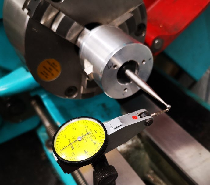
All operations were now complete and I mounted probe with its cable unplugged in the lather chuck with the new 19mm rod.  I mounted my dial gauge on the lathe bed and set about centralising the probe ball.  It was so much easier in the lathe with no cable to get in the way of things. Transferring the modified probe to the Tormach afterwards gave very similar centralising results.

Centralising the modified Wildhorse Innovations passive probe
Modified probe mounted in the lathe to allow easier access to the three centralising screws

So a typical workshop wormhole progression from job to job but as ever it was time well spent.

Similar or related subjects : –

Machining a job that is outside a milling machine’s table travel using Fusion 360

Introduction

This write up is not for the purists with years of experience but is an explanation of how I thought through how to machine something over size that would not fit into my Tormach PCNC440 milling footprint as a single operation.  Hopefully it might help others to grasp the process.

The challenge began when a local turret clock expert came to me and asked if I could machine a new Hour and Minute Hand for a clock he was working on.   The Hour Hand was around 14” long and the Minute Hand some 18” long.   

Here is the Fusion 360 view of the minute Hand.

clock minute hand milled in three steps

Clearly these lengths were way outside the 440 table X movement (10”) so a plan was needed.  There then followed a lot of staring into the distance at mealtimes and also at bedtime accompanied by vocal “hmmm”s as I tried to mentally visualise what was needed.  This idiosyncrasy is something my wife has come to terms with over the years…..

My conclusion from this mental preparation was that I needed to be able to accurately step the stock across the tooling table and then take two or three bites at the profile machining.  

What follows would almost certainly benefit from a video but sadly I am not set up for this. 

Click the link below to download the PDF document.

Milling an oversize object

Similar or related subjects : –

Automated Wheel Cutting GCode for the Tormach with the Sherline CNC Rotary Table

I have been putting this off as I thought it would be hassle and in fact it was very simple.

Here is the code which is the first time I have ever used a sub-routine.

The top section is my standard set up routine for the Tormach.

The middle section has some out of the way locations to try the idea so don’t get too fixated by these.   The important bit is the M98 call for the sub routine, the sub routine name (1001) and the number of repeats (the L5 for five repeats).

The last section is the sub routine indicated by the O1001.   The M64 command is specific to the Tormach USB Expansion board and it makes relay P0 in the box close its contact which in turn activates the Sherline CNC Rotary table to move one step.   The cutter than moves across to cut the tooth and then returns whereupon the relay drops out (M65), waits and then closes once more to increment the table.   Once five repeats have happened the M99 closes the sub routine and the program jumps back to the Z10 line in the middle section before stopping the spindle, homing and ending.

The joy of this method is that it is a simple edit of one line (the M98  instruction) to change the number of tooth cutting increments. I like it a lot.

Some fine tuning is still needed on the back and forth distances needed to clear the cutter through the wheel blank.

The normal test of the cut depth routine will still be needed before this could be run but once this is done it should be a sit and watch job.   Hopefully.

I have yet to run a wheel in anger so I will let you know how it goes. 

A compiled write up of all the related blog entries on this subject can be found on the downloads page.

Similar or related subjects : –

Cycloidal Cutters and Finding the Cutting Centre

It has been a thoughtful morning on the Tormach wheel cutting setup. 

In order to cut clock wheels the first step is that I need to be able to set the cycloidal cutter centre line accurately on the centre line of the blank brass diameter.  See the picture and description below.

Exaggerated mock up of the cutting setup showing a brass blank mounted on a super glue arbor and a cutter mounted in the Tormach Slitting Saw arbor. The centre line of the cycloidal cutter teeth sits on the centre line of the brass blank and cuts on the rear edge as seen above. After each cut the CNC rotary table increments the blank by one tooth ready for the next cut. (In practice the super glue arbor would need to be much larger in diameter in order to be more in keeping with the diameter of the brass blank and so ensure maximum support while the cutting was done).

From previous posts you will know I have got the chuck securely and centrally mounted on the CNC rotary table and this assembly is in turn rigidly fixed on the tooling table. The position of the centre line of the chuck is now fixed relative to the tooling plate on the bed.  The chuck and rotary table mounting bracket is sufficiently Woody over engineered to hopefully be repeatable.   Likewise the distance from the spindle to the chuck can be repeatably zeroed using the Haimer and its associated tool table entry (#90).

Expanding this a little, if I put my favourite piece of 11mm diameter silver steel in the chuck and bring the Haimer down to contact it, rock the Haimer back and forth in Y to get the steel diameter peak, I can get a Z zero reading to the top of the steel.   By creating a new entry in the Tormach tool table (#91) which is the Haimer length plus 5.5mm (the radius of the silver steel) I can use this virtual length stored as a new tool #91 to allow me to set the Haimer on the silver steel while actually giving me Z0 on the centre line of the chuck. So far so good.

As you might have read from an earlier post, the idea of using the Tormach Slitting Saw arbor to hold my cycloidal cutters would in theory create a repeatable tool length to the centre line of the cycloidal cutter teeth.   Having this as a tool table set up in the Tormach would simplify setting the cutter centre to the centre line of the chuck and therefore the  centre line of the wheel blank being cut. This is where the thinking drifted somewhat.   

I created a new tool table entry (#77) that was the length of the saw arbor to the shoulder that the cycloidal cutter fastens against.   I thought I could then follow the same routine as detailed above and add to this length the half thickness of the cutter and create a new tool table entry to match.  This would once again create a length which would give the centre line of the cycloidal cutter.

That was fine until I measured my tray of cycloidal cutters to see what the thickness of the cutters were …… sadly consistent they are not.   There seems to be no standard by manufacturer or diameter.   I have cutters with thicknesses from 3mm through to 7mm.   I could create a new tool table entry for each thickness but this is a recipe for a mistake when selecting the correct tool table entry for the cutter being used.

The simple solution I think is to use slitting saw arbor tool table length (#77) as the initial setting length to Z0 and then do a G0 Z-x.xx where x.xx is the half thickness of the cutter being used.   Once Z has dropped to this reading the Z axis can be re-zeroed to run the wheel in question with the cutter in question now sitting on its centre line on the centre line of the chuck.

Simple diagram showing the concept of using the Tormach tool table facility to allow easy setting of the centre line of a wheel blank and cycloidal cutter centre lines

I hope that all makes sense …. I could of course just eyeball it and not try to be so fussy but when you have the tools to make things easier you might as well use them.  I also need to look after my precious piece of 11mm diameter silver steel.

Similar or related subjects : –

Tormach USB Expansion Board boxed and mounted

Another piece of the clock wheel cutting hardware completed.

The Tormach USB expansion board is now boxed and the connectors wired to the board.   I milled a viewing window in the box with a matching piece of perspex.   This allows me to see the status LEDs on the pcb. Port #P0 is now dedicated to the Sherline CNC rotary table controller which requires a closure to increment the table stepper motor.   

The connectors are all 8 pin MiniDIN which matches the interface on the rotary table.

Tormach USB Expansion card mounted in an IP55 enclosure and on the blanking panel where the ATC would normally be fitted.
Internal view of the Tormach USB Expansion board mounted in its enclosure. It shows the MiniDIN connectors on the pcb milled using my vacuum table and also the lazy cable gland on the USB cable

Still got to do the GCode …

Similar or related subjects : –

Verified by ExactMetrics